Clamping device

A clamping device and a technology for clamping tools, which are applied in the accessories of tool holders, turning equipment, socket/socket connections, etc., can solve the problems of harmful, damping cavity accumulation of chips, unbalance, etc.

Active Publication Date: 2009-07-22
SCHUNK GMBH & CO KG
View PDF13 Cites 0 Cited by
  • Summary
  • Abstract
  • Description
  • Claims
  • Application Information

AI Technical Summary

Problems solved by technology

[0006] The disadvantage is that swarf etc. can accumulate in the damping cavity
Since the accumulation of swarf etc. is not uniform in the damping cavity, the accumulation of swarf necessarily leads to an unbalance which is detrimental in some high speed situations of the machine tool

Method used


Image

  • Clamping device
  • Clamping device
  • Clamping device

Examples


Embodiment Construction

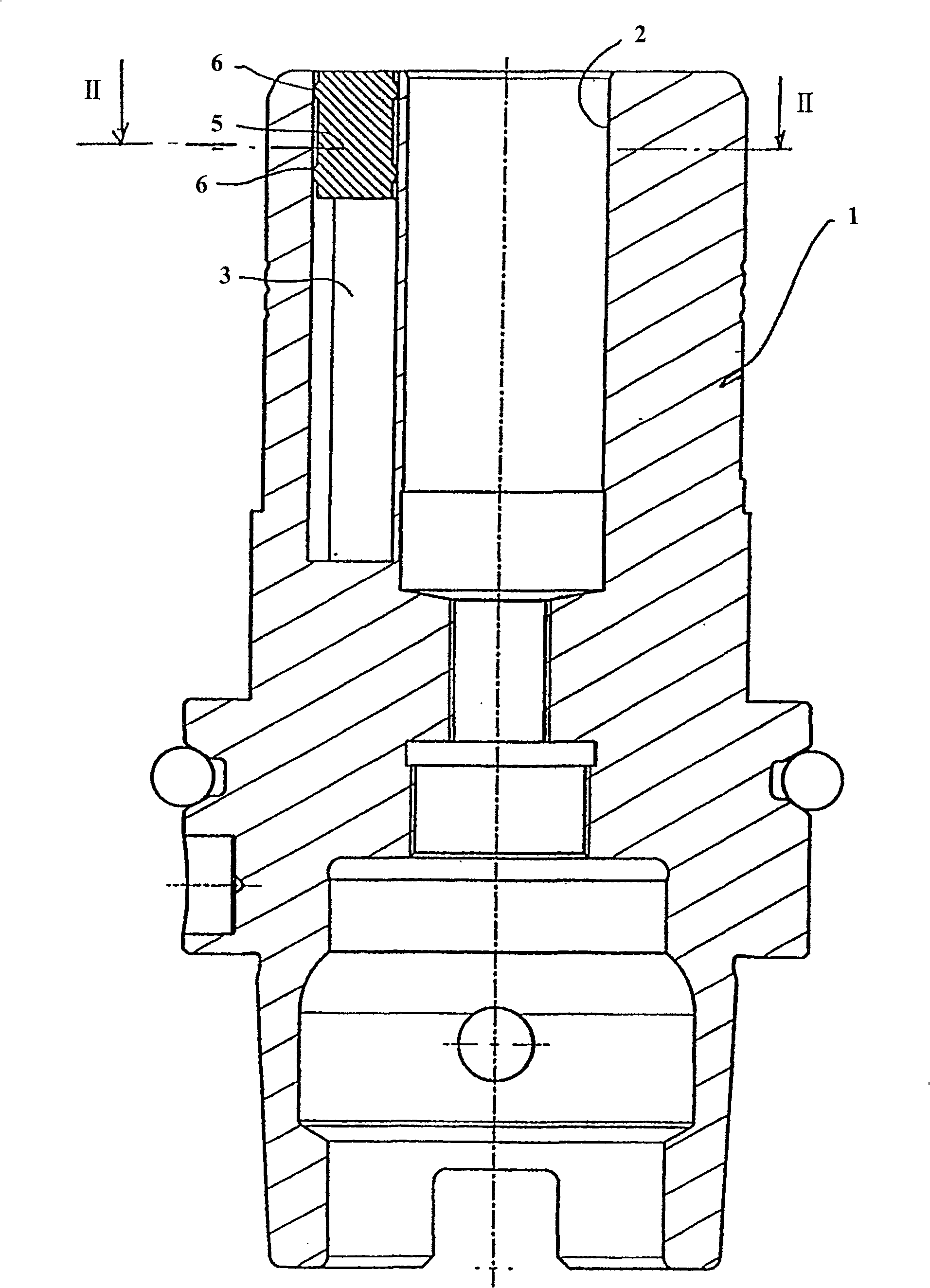
[0027] in figure 1 versus figure 2 Shown in is a longitudinal cross-sectional view of the first embodiment of the clamping device according to the aforementioned invention. The clamping device used to clamp the tool can be configured as a chuck, or it can be directly integrated into the work spindle of the machine tool, for example. . The chuck contains a chassis 1, which is made of a hard material such as steel. The chassis 1 has a central socket 2 in its end area. The socket 2 is used for the cylindrical tool holder of the tool W to be clamped, such as a drill tool holder. Or milling cutter arbor. The chassis 1 has a cutting position in its other end region according to a known method for clamping the tool holder to the work spindle of the machine tool.

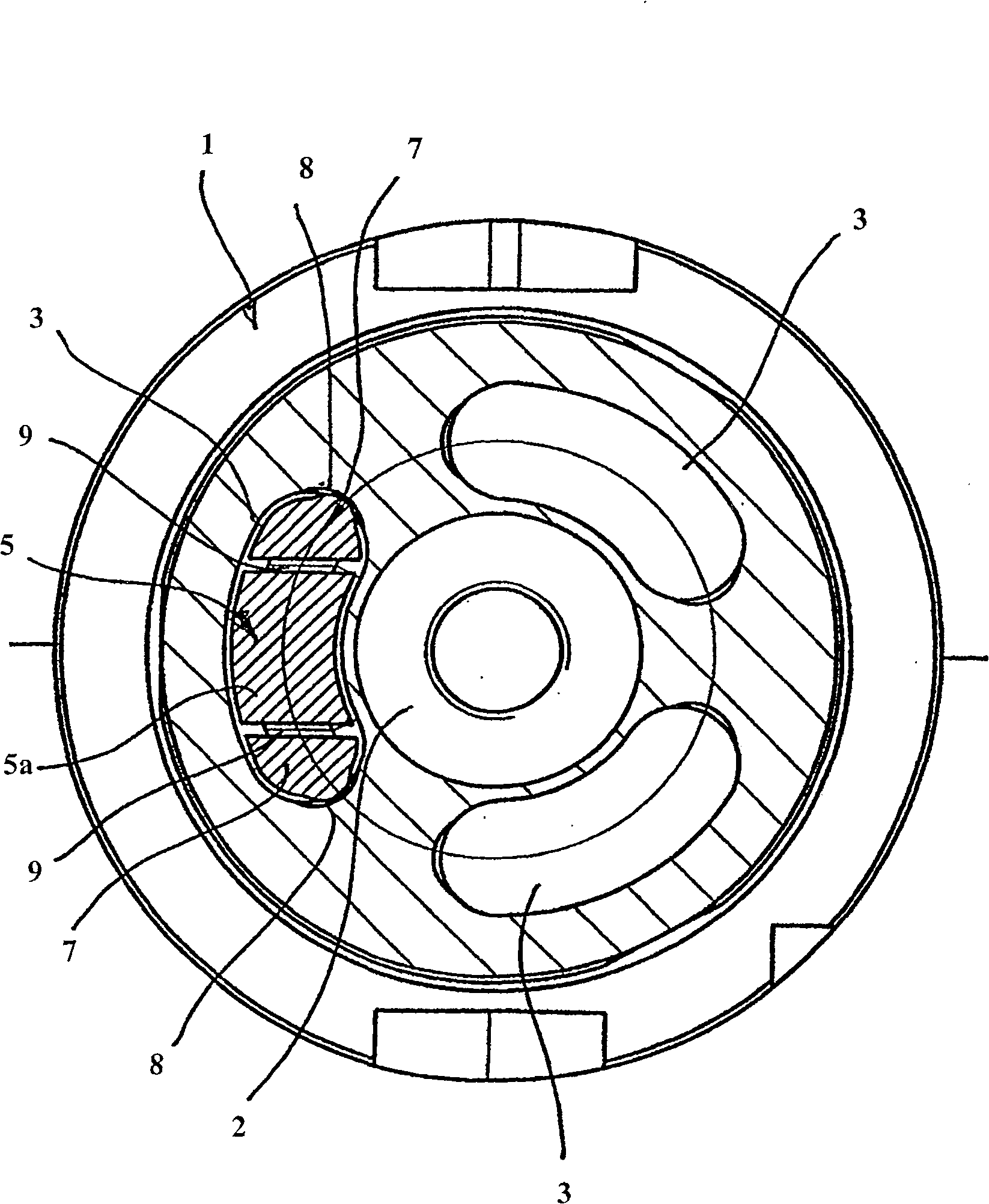
[0028] Three damping cavities 3 are evenly distributed around the socket 2 in the chassis 1. The damping cavity 3 opens toward the end surface of the chassis 1 on the tool side and forms an approximate kidney shape, wherein t...


PUM


Abstract

The device has a base (1) with a retainer (2), and annular damping cavities (3) arranged around the retainer and set off from each other. Each damping cavity is open towards a front face of a base facing a workpiece. The open end of each damping cavity is partially closed by respective covers (5). The covers are inserted into respective cavities from the open front face and fixed in O-rings.

Description

Technical field [0001] The invention relates to a clamping device for clamping tools, which has a chassis, in which a central socket for the tool holder of the tool to be clamped is provided, and a circular ring surrounding the socket is provided. The damping cavity may be provided with a plurality of damping cavities scattered around the socket and containing fillers, wherein each damping cavity is open to the tool side end surface of the chassis. Background technique [0002] Such a clamping device has been disclosed, for example, in WO 00 / 76703, and its function is to fix the tool shank, such as a drill tool shank or a milling tool shank, on the work spindle of the corresponding machine tool. This type of clamping device is specially provided for clamping smaller tools. [0003] In the clamping device disclosed in WO 00 / 76703, the tool is clamped by shrink fit. It is here in principle formed by a metal chassis, which has a central socket for clamping the tool holder. Among the...

Claims


Application Information

Patent Timeline
Patent Type & Authority Patents(China)
IPC IPC(8): B23B31/02
CPCY10T409/30952Y10T408/76B23B31/001Y10T409/304312Y10T408/95B23B2231/28B23B2250/16B23B31/1179Y10T279/17957
Inventor 托马斯·雷茨巴赫迈克尔·哈格
Owner SCHUNK GMBH & CO KG
Why Eureka
Try Eureka