Stator core, stator, motor and electric car

A stator core and stator technology, which is applied in the field of motors and electric vehicles, stator cores, and stators, can solve the problems of reducing the stiffness of the stator core, increasing the volume of the motor, and reducing the effective contact area, so as to achieve improved power density and uniform magnetic density distribution , the effect of increasing the area

Inactive Publication Date: 2019-03-19
NIO CO LTD
View PDF7 Cites 2 Cited by
  • Summary
  • Abstract
  • Description
  • Claims
  • Application Information

AI Technical Summary

Problems solved by technology

[0005] 1. One is to open an oil guide groove on the yoke of the stator core, so that the cooling oil can move along the axial direction of the stator core. This structure realizes the improvement of the power density through the cooling of the entire stator core by the cooling oil, but because the stator yoke The stiffness of the motor plays an important role in suppressing the vibration and noise of the motor. Setting the oil guide groove on the stator yoke will reduce the stiffness of the stator core, which is not conducive to suppressing the vibration and noise of the motor.
[0006] 2. One is to set up a spiral groove structure on the outside of the stator core, so that the cooling oil can move along the outside of the stator core to realize heat transfer and cooling. Although this method can improve the heat dissipation of the motor, it virtually increases the outer diameter of the motor. As a result, the volume of the motor increases. At the same time, since the motor stator core and the casing are fixed together through interference fit, too many oil guide grooves are opened, which reduces the effective contact area between the outer diameter of the stator core and the inner diameter of the casing. It will reduce the torsional bearing force between the two, and there is a risk of relative rotation between the stator core and the casing when the torque of the high-torque motor is transmitted

Method used


Image

  • Stator core, stator, motor and electric car

Examples


Embodiment Construction

[0030] In order to make the object, technical solution and advantages of the present invention clearer, the present invention will be further described in detail below in combination with specific embodiments and with reference to the accompanying drawings. It should be understood that these descriptions are exemplary only, and are not intended to limit the scope of the present invention. Also, in the following description, descriptions of well-known structures and techniques are omitted to avoid unnecessarily obscuring the concept of the present invention.

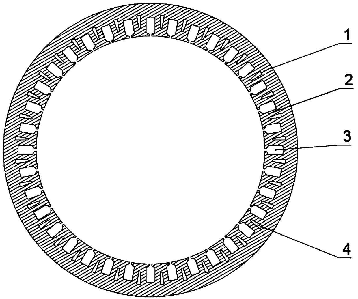
[0031] figure 1 A schematic structural diagram of a stator core provided by an embodiment of the present invention.

[0032] Please refer to figure 1 , In an embodiment of the present invention, a stator core is provided, including: a yoke 1 and a plurality of teeth 2 .

[0033] The yoke 1 is a ring-shaped structure; a plurality of teeth 2 are evenly distributed on the inner side of the yoke 1 along the circumferential...


PUM


Abstract

The invention discloses a stator core, belonging to the technical field of motors. The stator core comprises: a yoke portion (1) and a plurality of tooth portions (2); the plurality of tooth portions(2) are evenly distributed on the inner side of the yoke portion (1) in the circumferential direction and extending in the radial direction of the yoke portion (1); a stator slot (3) is formed betweenthe two adjacent tooth portions (2); an end, close to the yoke portion (1), of the tooth portions (2) are provided with oil guide grooves (4) extended along the axial direction. The stator cores of the invention is provided with the oil guide grooves at the tooth portions to allow the cooling oil to conveniently enter the stator core through the oil guide grooves, increase the area of the coolingoil contacting the heat source, effectively improve the heat dissipation of the stator core without affect of the rigidity of the stator core and the interference assembly process between the statorcore and the casing; at the same time, the oil guide grooves are arranged at the tooth portions without increasing of the volume of the motor so that the motor can be lightweight.

Description

technical field [0001] The invention relates to the technical field of motors, in particular to a stator core, a stator, a motor and an electric vehicle. Background technique [0002] At present, with the rapid development of electric vehicles, a new round of motor innovation has been triggered. Permanent magnet motors have been widely used in electric vehicles due to their advantages such as high efficiency and high power density. [0003] The requirement of high power density of the motor inevitably requires the development of the motor towards high-speed miniaturization, and the high-speed miniaturization brings about an increase in the temperature rise of the motor. In the prior art, the casing water cooling method is generally used to cool the motor, but the cooling This method restricts the further improvement of the power density of the motor. [0004] In order to solve the above-mentioned problems, the prior art usually adopts an oil-cooled motor structure, by spray...

Claims


Application Information

Patent Timeline
Patent Type & Authority Applications(China)
IPC IPC(8): H02K1/16H02K1/20
CPCH02K1/165H02K1/20Y02T10/64
Inventor 张胜川
Owner NIO CO LTD
Why Eureka
Try Eureka