
Illumination system

A lighting system and light collimation technology, applied in the field of lighting systems, can solve the problem of not being able to change the beam pattern

Inactive Publication Date: 2009-04-29
KONINK PHILIPS ELECTRONICS NV
View PDF6 Cites 0 Cited by
  • Summary
  • Abstract
  • Description
  • Claims
  • Application Information

AI Technical Summary

Problems solved by technology

[0005] A disadvantage of the known lighting system is that it is not possible to change the beam pattern emitted by the lighting system

Method used


Image

  • Illumination system
  • Illumination system
  • Illumination system

Examples


Embodiment Construction

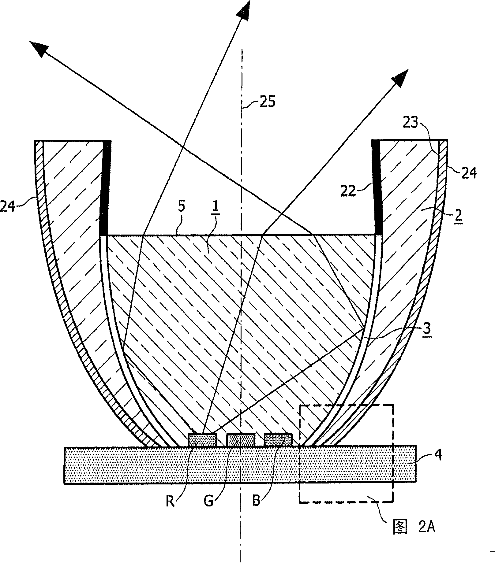
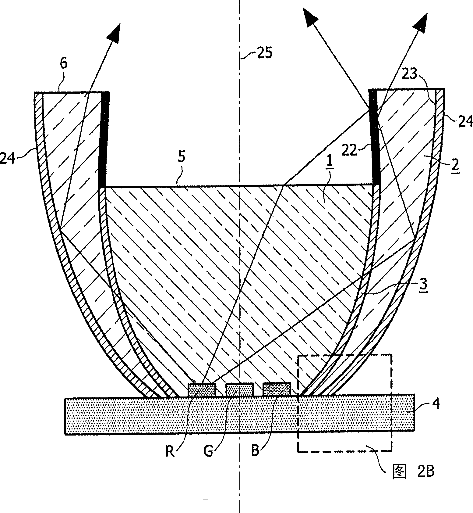
[0043] Figure 1A A cross-sectional view of a first embodiment of a lighting system according to the invention is schematically shown. Figure 1B schematically shows Figure 1A A cross-sectional view of an embodiment of the illumination system shown in , in a mode of operation that enhances the effect of the second light collimator.

[0044] Figure 1A and 1B The lighting system in the LED includes a plurality of light sources, such as a plurality of light emitting diodes (LEDs). LEDs can be light sources of different primary colors, such as in Figure 1A and 1B Examples of these are the well known red R, green G or blue B light emitters. Alternatively, the light emitter may have, for example, amber or cyan as a primary color. These primary colors can be produced directly by the LED chips, or by phosphors under irradiation with light from the LED chips. In the latter case, mixed colors or white light can also be used as a primary color of the lighting system. exist Figur...


PUM


Abstract

An illumination system has a plurality of light emitters (R5G5B), a first light collimator (1) for collimating the light emitted by the light emitters, and a first light collimator (1) for collimating the light emitted by the light emitters. Straight at least the second optical collimator (2). The first optical collimator is arranged around the longitudinal axis (25) of the illumination system, and the second optical collimator is arranged around the first optical collimator along the longitudinal axis. Light propagation in the first optical collimator is based on total internal reflection. The propagation of light in the second light collimator is based on total internal reflection or reflection at the outer surface of the second light collimator remote from the longitudinal axis. A cavity (3) is provided between the first and second optical collimators. The cavity has an electrowetting-based switchable optical element, wherein the switchable optical element is switchable in an operating mode that reduces the effect of the second light collimator.

Description

technical field [0001] The invention relates to an illumination system comprising a plurality of light emitters and at least one first light collimator for collimating light emitted by a light reflector. Background technique [0002] Such lighting systems are known per se. In particular it is used for general lighting purposes, such as spotlights, accent lighting, floodlights, and it is used for large-area direct-view light-emitting panels, as in applications such as signs, contour lighting and billboards. In other applications, the light emitted by such an illumination system is routed into an optical waveguide, fiber optic or other beam shaping optics. In addition, such lighting systems are used as backlighting for (image) display devices, such as television receivers and monitors. Such lighting systems can be used as backlights for non-emissive displays such as liquid crystal display devices, also called LCD panels, which are used in (portable) computers or (cordless) t...

Claims


Application Information

Patent Timeline
Patent Type & Authority Patents(China)
IPC IPC(8): G02B6/42F21V8/00G02B26/00H01L33/58H01L33/60
CPCF21V5/04H01L25/0753F21Y2113/005F21Y2105/001G02B26/005F21V14/003F21V7/0091H01L33/58F21Y2101/02H01L33/60G02B26/004H01L2924/0002F21Y2105/10F21Y2115/10F21Y2113/13H01L2924/00
Inventor C·G·A·霍伦J·P·M·安森斯S·凯帕
Owner KONINK PHILIPS ELECTRONICS NV
Learn More