
Miller-compensated amplifier

A Miller compensation, amplifier technology, applied in amplifiers, amplifiers with semiconductor devices/discharge tubes, improving amplifiers to reduce the harmful effects of internal resistance, etc., can solve the problem of reducing the product of the gain and bandwidth of the compensation amplifier.

Active Publication Date: 2009-04-01
MEDIATEK INC
View PDF2 Cites 0 Cited by
  • Summary
  • Abstract
  • Description
  • Claims
  • Application Information

AI Technical Summary

Problems solved by technology

However, the gain-bandwidth product of the compensating amplifier decreases as the capacitance increases

Method used


Image

  • Miller-compensated amplifier
  • Miller-compensated amplifier
  • Miller-compensated amplifier

Examples


Embodiment

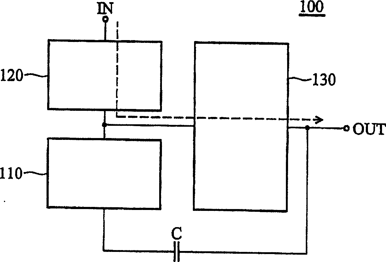
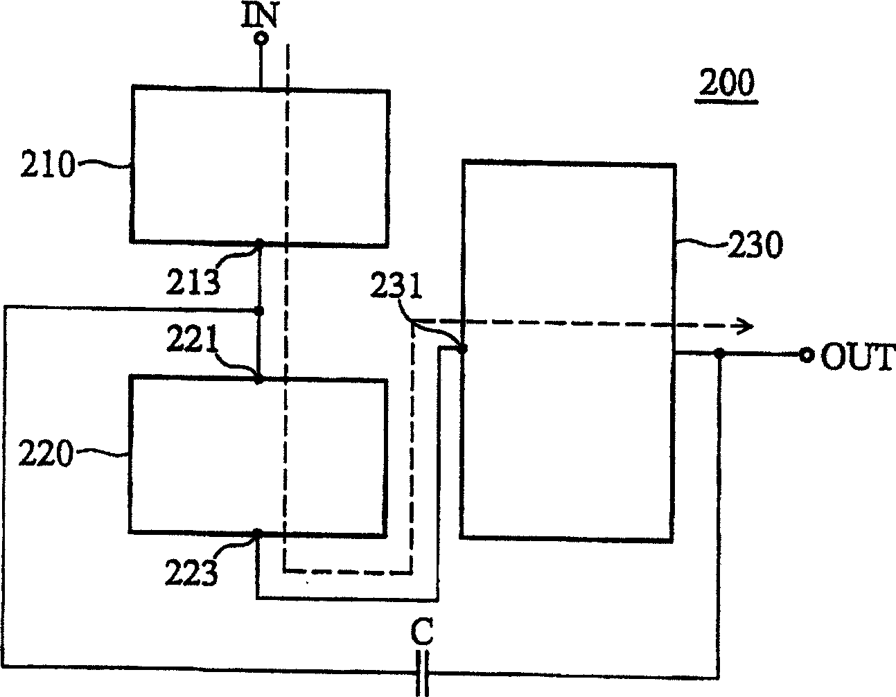
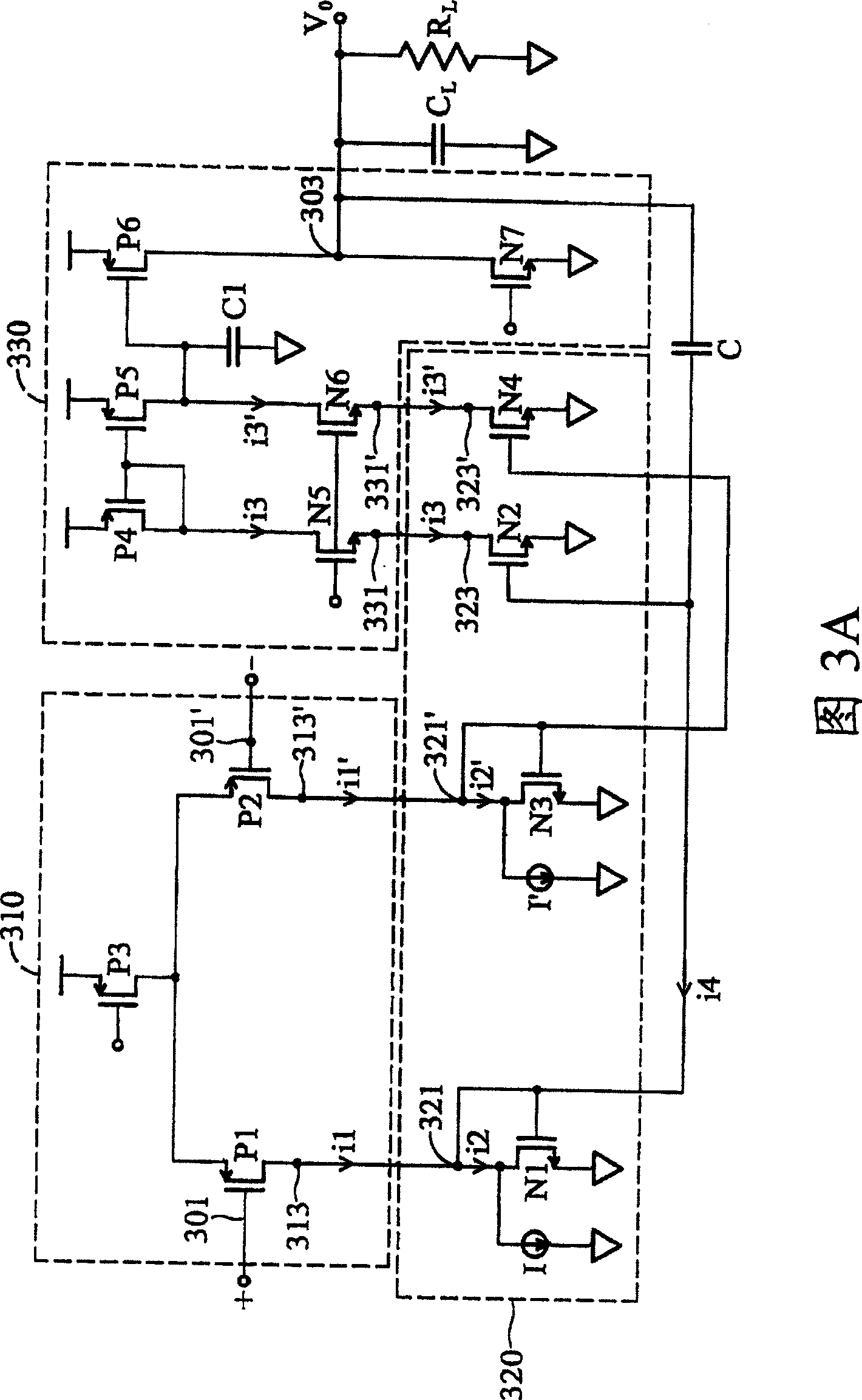
[0031] figure 2 A Miller-compensated amplifier according to an embodiment of the invention is shown. The Miller compensation amplifier 200 has an amplifier input terminal IN and an amplifier output terminal OUT, and includes a first gain stage 210 , a second gain stage 220 , a third gain stage 230 and a capacitor C. The first gain stage 210 has an amplifier input IN as the first gain stage input and a first gain stage output 213 . The second gain stage 220 has a second gain stage input 221 coupled to the first gain stage output 213 and a second gain stage output 223 . The third gain stage 230 has a third gain stage input 231 coupled to the second gain stage output 223 and generates an output terminal voltage at the amplifier output OUT. The capacitor C is coupled between the output terminal OUT of the amplifier and the input terminal 221 of the second gain stage. The second gain stage 220 amplifies the small signal part of the received partial current i by a first gain, an...


PUM


Abstract

A Miller-compensated amplifier, having an amplifier input and an amplifier output, comprises a first gain stage, a second gain stage, a third gain stage, and a capacitor. The first gain stage has the amplifier input as a first gain stage input thereto and a first gain stage output. The second gain stage has a second gain stage input, coupled to the first gain stage output, and a second gain stage output. The third gain stage has a third gain stage input, coupled to the second gain stage output, and provides an output voltage at the amplifier output. The capacitor is coupled between the amplifier output and the second gain stage input. The Miller-compensated amplifier provided by the invention separates pole of the amplifier by adding a Miller-compensated capacitor so as to improving the stability of the negative feedback loop, and can keep constant gain-bandwidth product of the amplifier without reducing frequency width.

Description

technical field [0001] The present invention relates to a frequency compensation circuit, in particular to a circuit with compensation capacitance. Background technique [0002] The stability of circuit feedback can be improved by compensating for the increased phase margin. A well-known method for improving the phase boundary value is to use the Miller effect to add a Miller compensation capacitor parallel to the gain stage, for example, at the output stage of a two-stage amplifier circuit. The configuration result in the well known and desired pole splitting phenomenon helps to multiply the effective capacitance of the physical capacitors in the circuit. Chapter 9 (particularly pp. 607-623) of "Analysis and Design of Analog Circuits, Third Edition," by R. Gray and Robert G. Meyer, John Wiley & Sons, Inc., New York, 1993 The technical background of using the Miller compensation capacitor as the compensation of the amplifier circuit is disclosed in . [0003] In US Pat. N...

Claims


Application Information

Patent Timeline
Patent Type & Authority Patents(China)
IPC IPC(8): H03F1/08
CPCH03F3/45183H03F1/086
Inventor 陈弘易楼志宏
Owner MEDIATEK INC
Learn More