Excess optical carrier grating

A technology of optical carriers and gratings, applied in the field of optical information, can solve problems such as difficult to balance flat field and high resolution, low optical efficiency, and low light intensity, and achieve strong grating spectral ability, good frequency resolution, and flexibility good sex effect

Inactive Publication Date: 2009-03-18
UNIV OF ELECTRONICS SCI & TECH OF CHINA
View PDF5 Cites 0 Cited by
  • Summary
  • Abstract
  • Description
  • Claims
  • Application Information

AI Technical Summary

Problems solved by technology

The disadvantage of the transmission grating is: due to the effect of the single-slit diffraction factor, the zero-order main pole without dispersion in the diffraction pattern occupies a large part of the total light energy, and the rest of the light energy has to be dispersed into all levels of spectrum, so that each level The light intensity of the spectrum is relatively small, and the higher the order, the weaker the light intensity
The planar reflection grating can stagger the 0th order of single-slit diffraction and the 0th order of interslit interference, so as to transfer the light energy to a required spectral line (making the zeroth order a missing order), and its disadvantages are: low light efficiency and Due to the serious inhomogeneity of dispersion to wavelength, the secondary spectrum must be eliminated, usually two transverse gratings are required to work separately in different wavelength bands to obtain suitable transverse dispersion
The concave reflective grating can act as a dispersive element and a collimator, focusing the dispersed beam on the exit slit to obtain a sharp-line spectrum. The disadvantage is that it is difficult to balance the requirements of flat field and high resolution, resulting in aberrations Too big, not widely adopted

Method used


Image

  • Excess optical carrier grating
  • Excess optical carrier grating
  • Excess optical carrier grating

Examples


Embodiment Construction

[0012] The present invention will be further described below in conjunction with the accompanying drawings.

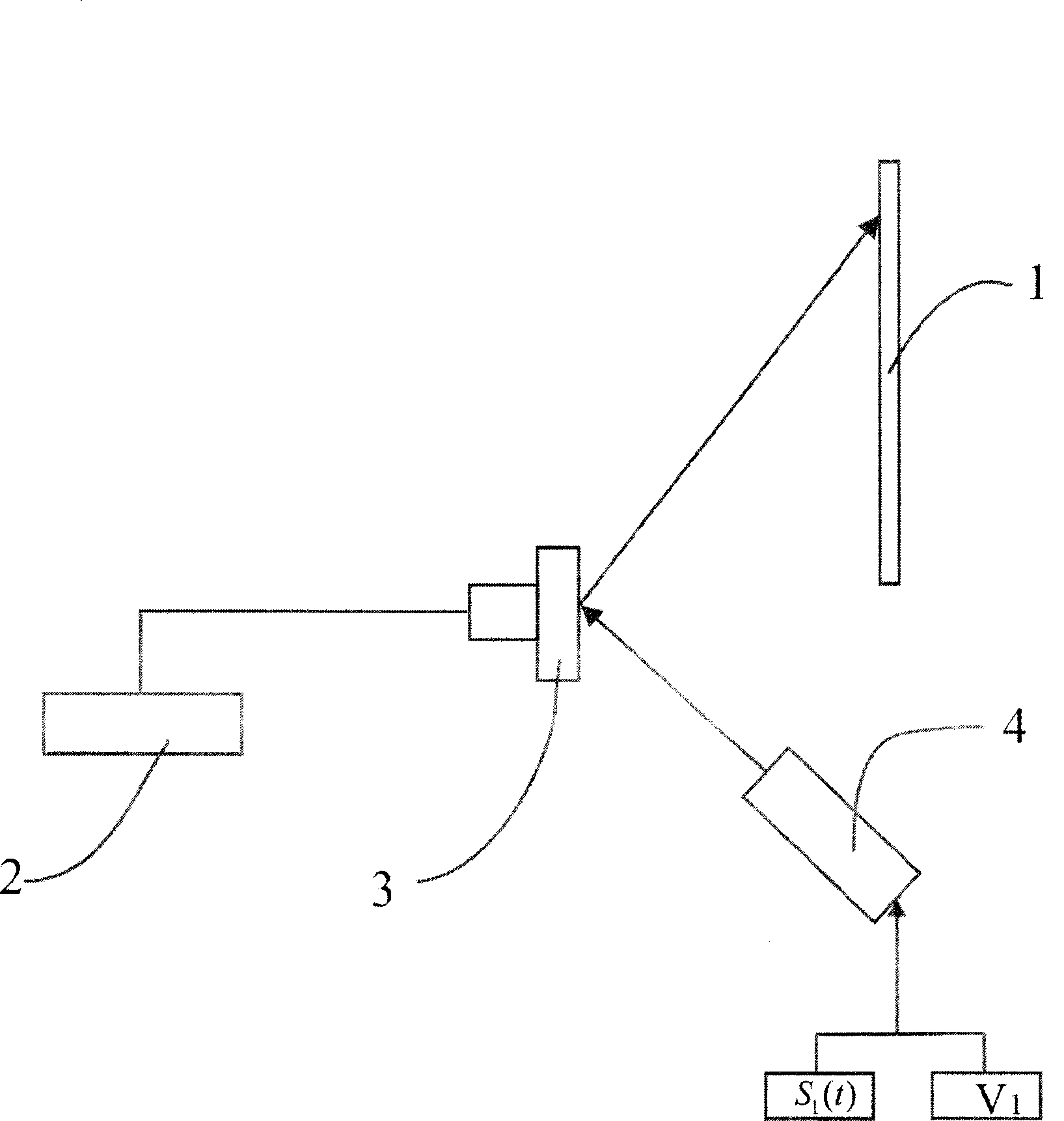
[0013] Such as figure 1 As shown, it includes from left to right from top to bottom: silicon wafer 1, scanning driver 2, vibrating mirror 3, excitation light source 4, scanning driver 2 drives the vibrating mirror 3 to rotate periodically, and the excitation light source 4 passes through the vibrating mirror 3. The reflected light is incident on the silicon chip 1, and the radio frequency electrical signal s 1 (t) added to the bias voltage v 1 on, and used to modulate the excitation light source. The excitation light source is a laser with a light wavelength of 830nm, and a heavily doped silicon wafer is selected.

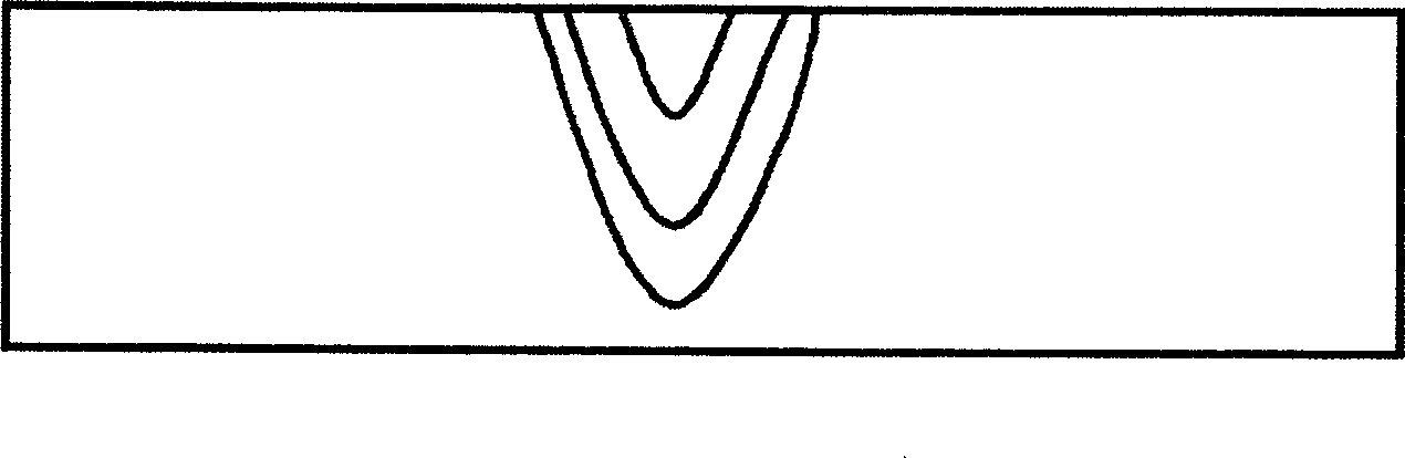
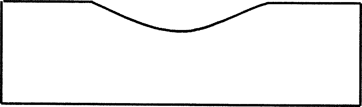
[0014] The formation mechanism of excess photocarrier grating: After the excitation light is incident on the silicon wafer, carriers are injected, and when the carrier concentration reaches equilibrium, the concentration distribution is as follows: fig...


PUM


Abstract

The invention discloses an excess light carrier grating which comprises a silicon wafer, a scanning driver, a vibratory mirror and an excited light source. The excited light source is refracted to the silicon wafer through a reflex of the vibratory mirror. The scanning driver is connected with the vibratory mirror to drive the vibratory mirror to rotate periodically and a radio frequency signal is added on a bias voltage to regulate the excited light source. The invention has the advantages that: 1) a constant is adjustable and flexible; therefore the invention can be applied to such systems as a correlator and a spectrum analyzer. 2) the constant can be very small, that means that the grating splitter ability is very strong and a frequency resolution is very good.

Description

technical field [0001] The invention relates to the field of optical information technology, in particular to an excess optical carrier grating. Background technique [0002] Gratings are mainly used in the field of optical information processing. Gratings are divided into two categories according to their working methods, one is transmission grating and the other is reflection grating. If it is classified according to its modulation effect on incident light, it can be divided into amplitude grating and phase grating. The current common transmission grating is to carve a series of equal-width and equal-spaced notches on the flat glass. The disadvantage of the transmission grating is: due to the effect of the single-slit diffraction factor, the zero-order main pole without dispersion in the diffraction pattern occupies a large part of the total light energy, and the rest of the light energy has to be dispersed into all levels of spectrum, so that each level The light inten...

Claims


Application Information

Patent Timeline
Patent Type & Authority Patents(China)
IPC IPC(8): G02B5/18G01R23/16G02B26/10H01S3/00
Inventor 高椿明王亚非赵斌兴周鹰杨立峰
Owner UNIV OF ELECTRONICS SCI & TECH OF CHINA
Why Eureka
Try Eureka