
A gear type compressor

A gear type and compressor technology, applied in the field of compressors, can solve problems such as bearing damage, achieve the effects of reducing vibration and noise, low price, and small compression ratio

Inactive Publication Date: 2009-03-04
LG ELECTRONICS (TIANJIN) APPLIANCES CO LTD
View PDF6 Cites 0 Cited by
  • Summary
  • Abstract
  • Description
  • Claims
  • Application Information

AI Technical Summary

Problems solved by technology

In addition, when the pressure changes sharply, it is easy to cause bearing damage

Method used


Image

  • A gear type compressor
  • A gear type compressor
  • A gear type compressor

Examples


Embodiment Construction

[0049] Below, refer to Figure 3 to Figure 7 , the embodiments provided by the present invention will be described in detail.

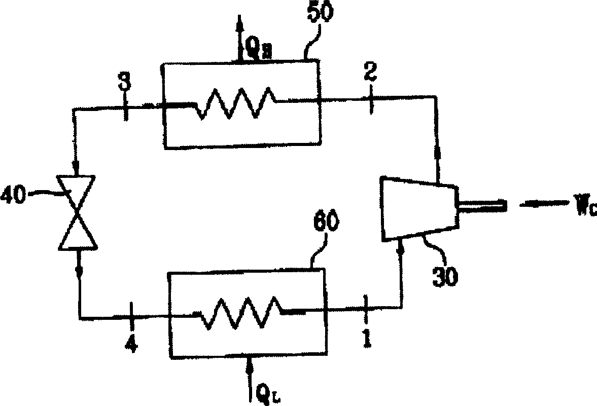
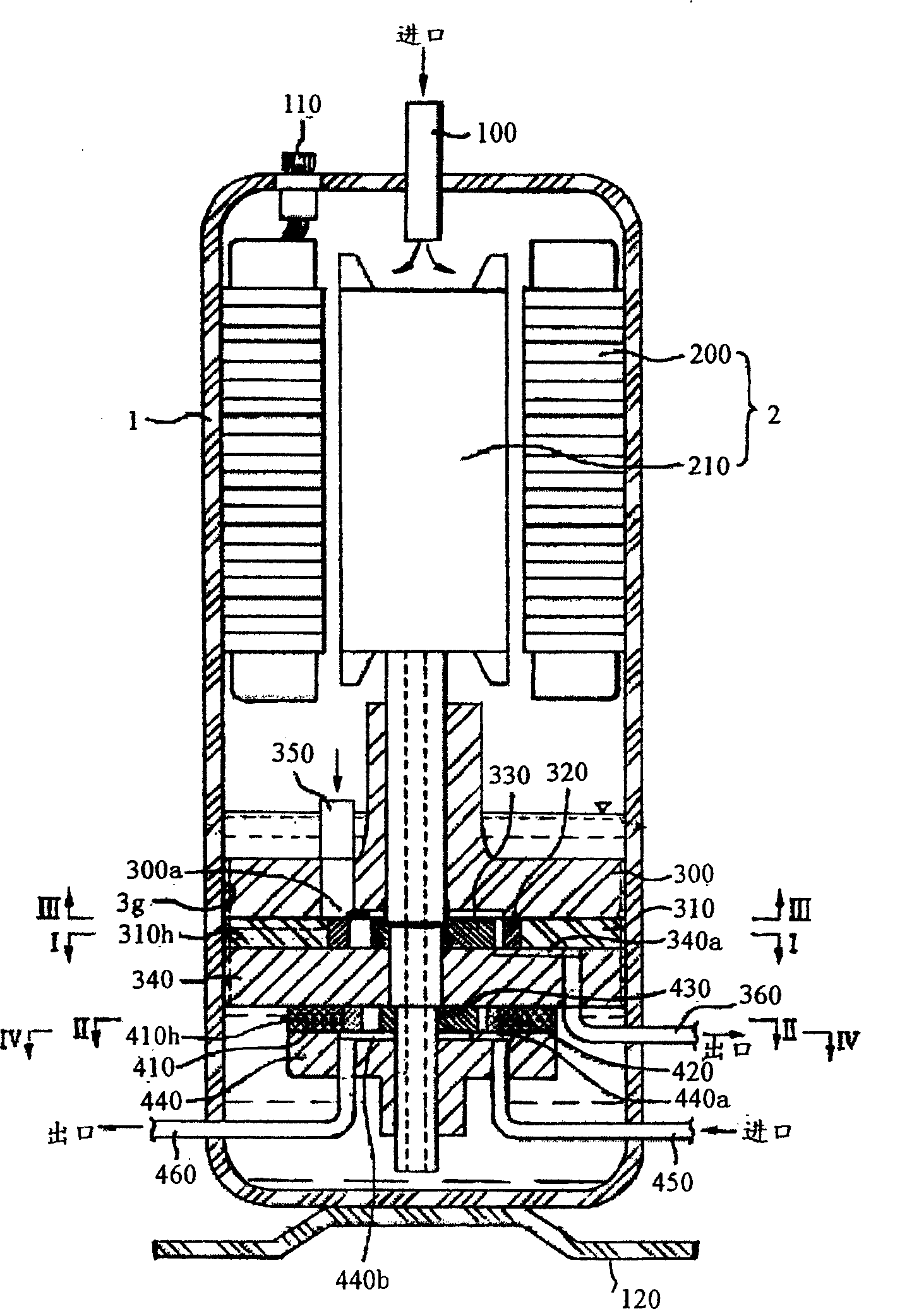
[0050] image 3 It is a schematic block diagram of the structure of the gear compressor of the present invention, Figure 4A for image 3 The I-I cross-sectional view, Figure 4B for image 3 II-II cross-sectional view, Figure 6It is a block diagram for adopting the compressor refrigeration system provided by the present invention.

[0051] As shown in the figure, the gear-type compressor in the present invention includes a casing 1 , a motor 2 , a gear-type compression part 3 , and a gear-type expansion part 4 . The casing 1 has a certain inner space, and the motor 2 is arranged inside the casing 1 . The gear-type compression part 3 uses the power provided by the motor 2 to compress the refrigerant discharged from the evaporator 6 . The refrigerant discharged from the compression part 3 flows through the condenser 5 and then flows into the c...


PUM


Abstract

A gear compressor comprises a shell and an inner motor installed inside the shell, a gear compressing section drove by the motor to compress the cold media from the evaporator, a gear inflation section to expand the cold media flowing from the condenser. The ratio of the outlet area of the compressing board in the compressing section to the inlet area of the main shaft is 1:1.3 ~ 1:3. The ratio of the inlet area to the outlet area of the sub shaft in the inflation section is 1:1.3 ~ 1:3.

Description

technical field [0001] The present invention relates to compressors, in particular to gear-type compressors. Background technique [0002] Generally, a compressor is a machine that uses the power of a motor or a steam turbine to pressurize working fluids such as air and refrigerant to increase the pressure of the working fluid. This kind of compressor is widely used in the fields of home appliances such as air conditioners and refrigerators, as well as in production fields. [0003] According to the type of compression, the compressor can be divided into positive displacement compressor and turbo compressor. Among them, the volumetric compressor is widely used in the production field, and the volumetric compressor is a working method that increases pressure by reducing volume. Volumetric compressors can be classified into reciprocating compressors and rotary compressors. [0004] The above-mentioned reciprocating compressor uses the reciprocating motion of the piston insi...

Claims


Application Information

Patent Timeline
Patent Type & Authority Patents(China)
IPC IPC(8): F04C18/10
Inventor 裴永周金京浩车江昱江胜民
Owner LG ELECTRONICS (TIANJIN) APPLIANCES CO LTD
Learn More