
Wire hook former

A molding device and wire hook technology, applied in the field of machinery, can solve the problems of frequent replacement of semi-finished products, large occupied area, and low production efficiency, and achieve the effects of fast production speed, good molding consistency, and high work efficiency

Inactive Publication Date: 2008-12-10
ZHEJIANG TOPSUN LOGISTIC CONTROL CO LTD
View PDF5 Cites 1 Cited by
  • Summary
  • Abstract
  • Description
  • Claims
  • Application Information

AI Technical Summary

Problems solved by technology

As a result, it takes up a large area of ​​the site, many production equipment, frequent replacement of semi-finished products and processing locations, low production efficiency, large waste, and high product processing costs.

Method used


Image

  • Wire hook former
  • Wire hook former
  • Wire hook former

Examples


Embodiment Construction

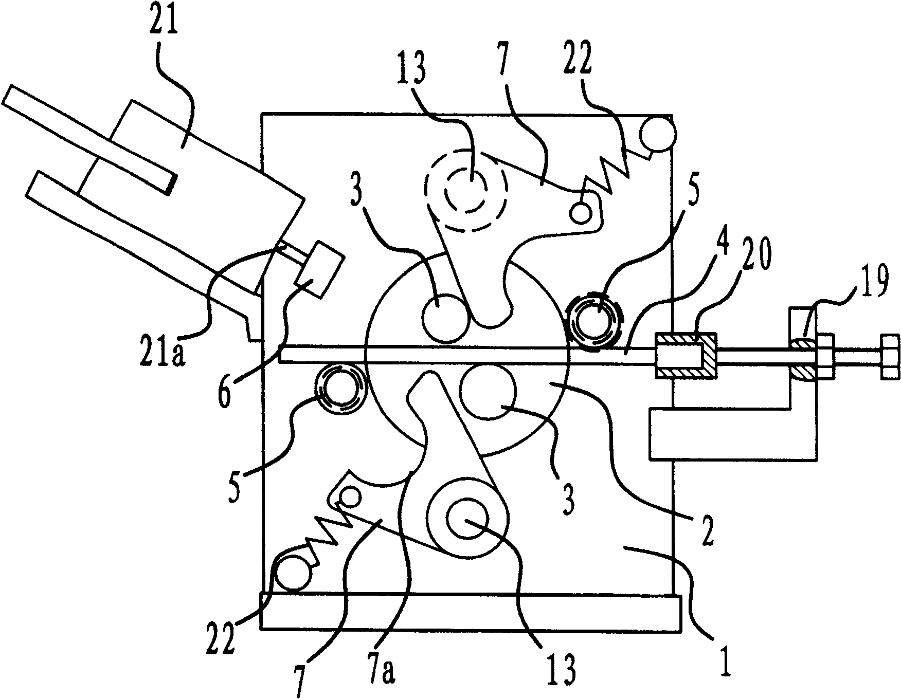
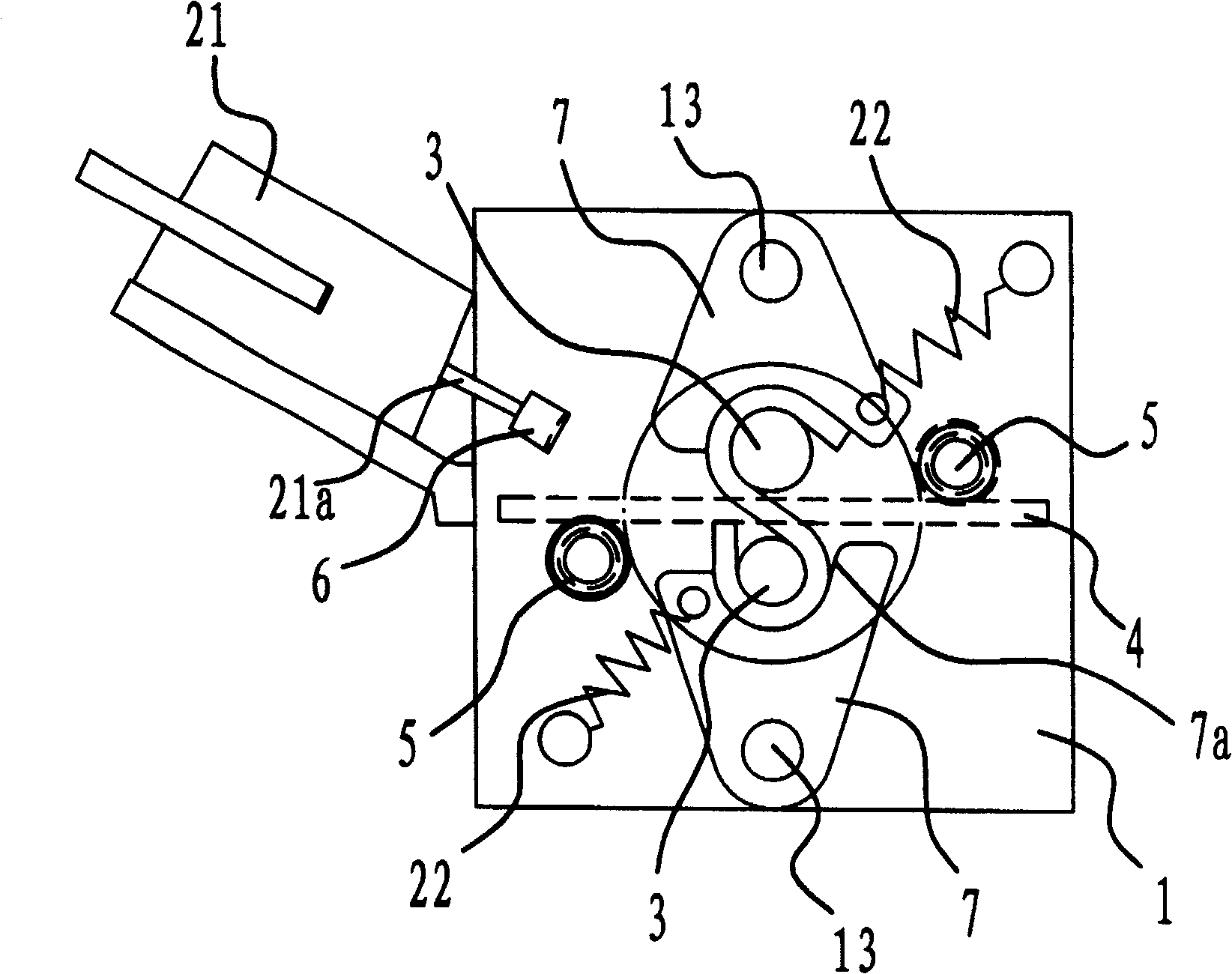
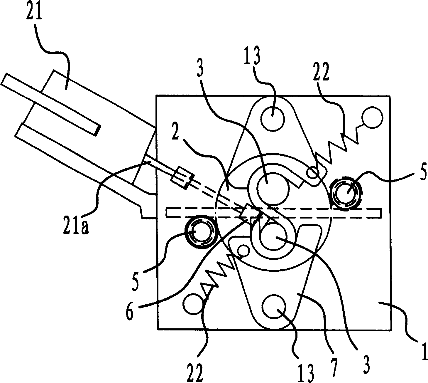
[0031] Such as Figure 1 to Figure 5 As shown, the wire hook forming device includes a forming seat 1 and a rotating disk 2 arranged thereon. The turntable 2 is provided with two staggered forming twist wheels 3 which can rotate with the turntable 2 , and there is a gap between the two forming twist wheels 3 for the wire 4 to pass through. On the forming seat 1, there are two forming retaining wheels 5 which are located at the periphery of the turntable 2 and can block the two ends of the wire 4, and a retractable pressing block 6 is arranged on one side of one of the forming retaining wheels 5. The top pressing block 6 is fixed on the end of the push rod 21a of the hydraulic cylinder 21 . Two rotatable forming plates 7 with arc-shaped notches 7a are symmetrically arranged on the periphery of the turntable 2 . The forming plate 7 is hinged on the forming seat 1 through a pivot 13 , and a tension spring 22 is arranged between the forming plate 7 and the forming seat 1 . One ...


PUM


Abstract

The present invention is one wire hook former and belongs to the field of mechanical technology. The wire hook former includes one forming seat, one turntable set on the forming seat, two crossed forming twisting wheels on the turntable to rotate with the turntable and with gap in between for wire material to pass through, two wire material holding wheels located outside the turntable and on the forming seat, one telescopic pushing block beside one holding wheel, and two rotary forming plates with arc notch set symmetrically outside the turntable. The wire hook former has high work efficiency, relatively low manufacture cost and capacity of realizing automatic production.

Description

technical field [0001] The invention relates to the technical field of machinery, in particular to a forming device for production line hooks. Background technique [0002] The wire hook is an indispensable part of the bundler, wire tensioner and other instruments. The shape of the hook is as Figure 6-1 and Figure 6-2 As shown, the entire wire hook is formed by stamping and bending a metal wire or plate. [0003] At present, wire hooks generally use four processes during production, namely straightening, material cutting, bending into an S shape, and hook and loop forming. These four processes are completed through independent production equipment and molds. Wire hook forming dies can generally solve the problem of initial molding, but there are inaccurate positioning, and the bent hook rings have differences in shape and inconsistent specifications, which are difficult to adapt to industrial production. At the same time, straightening and material cutting still need d...

Claims


Application Information

Patent Timeline
Patent Type & Authority Patents(China)
IPC IPC(8): B21F45/16B21F1/06
Inventor 阮卜琴
Owner ZHEJIANG TOPSUN LOGISTIC CONTROL CO LTD
Learn More