
Fluorescent optical imaging device

An optical imaging and fluorescence technology, used in fluorescence/phosphorescence, measurement devices, material analysis by optical means, etc., can solve the problems of inability to change the direction of excitation light irradiation according to needs, complex operation process, large operation space, etc. Simple, easy to operate, flexible configuration effects

Inactive Publication Date: 2008-10-08
HUAZHONG UNIV OF SCI & TECH
View PDF4 Cites 2 Cited by
  • Summary
  • Abstract
  • Description
  • Claims
  • Application Information

AI Technical Summary

Problems solved by technology

With this non-multi-directional lighting method, the part of the object close to the objective lens will block the part away from the objective lens, and the excitation light irradiation direction cannot be changed as needed during imaging.
[0007] (2) It is difficult to directly perform overall fluorescence optical imaging of objects larger than 30mm*40mm in size
[0008] (3) The change of the optical magnification of the imaging system needs to be done through a stereoscopic fluorescence microscope, while the setting of imaging detector parameters such as exposure time must be done through a computer. These two steps are separated and not controlled by the same equipment such as a computer. , the operation process is complicated
[0009] (4) Not light-tight, need to work in a dark room
When opening the door of the box, the operator must keep a relatively large distance from the light-tight box, that is, there must be a large operating space during operation.

Method used


Image

  • Fluorescent optical imaging device
  • Fluorescent optical imaging device
  • Fluorescent optical imaging device

Examples


Embodiment Construction

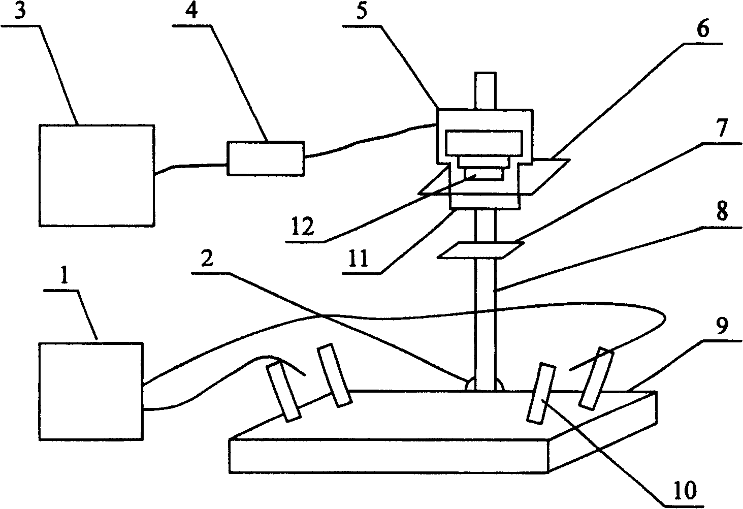
[0040] Depend on figure 1 As shown, the present invention is composed of an excitation light source 1, an imaging module 5, an imaging support, an optical airtight box and a control part.

[0041] The excitation light source 1 generates excitation light for exciting fluorescence, and the excitation light is irradiated onto the object to be imaged placed on the base 9 to excite the fluorescence of the object to be imaged.

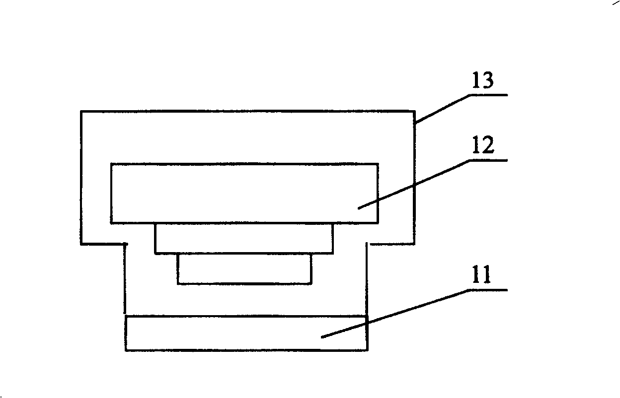
[0042] The imaging module 5 includes an imaging detector 12 and a fluorescence filter 11. The fluorescence filter 11 is placed in front of the imaging detector 12, and the reflected excitation light and the fluorescence emitted by the object to be imaged are irradiated to the fluorescence filter 11. The excitation light is filtered by the fluorescence filter 11 , and the fluorescence enters the imaging detector 12 through the fluorescence filter 11 .

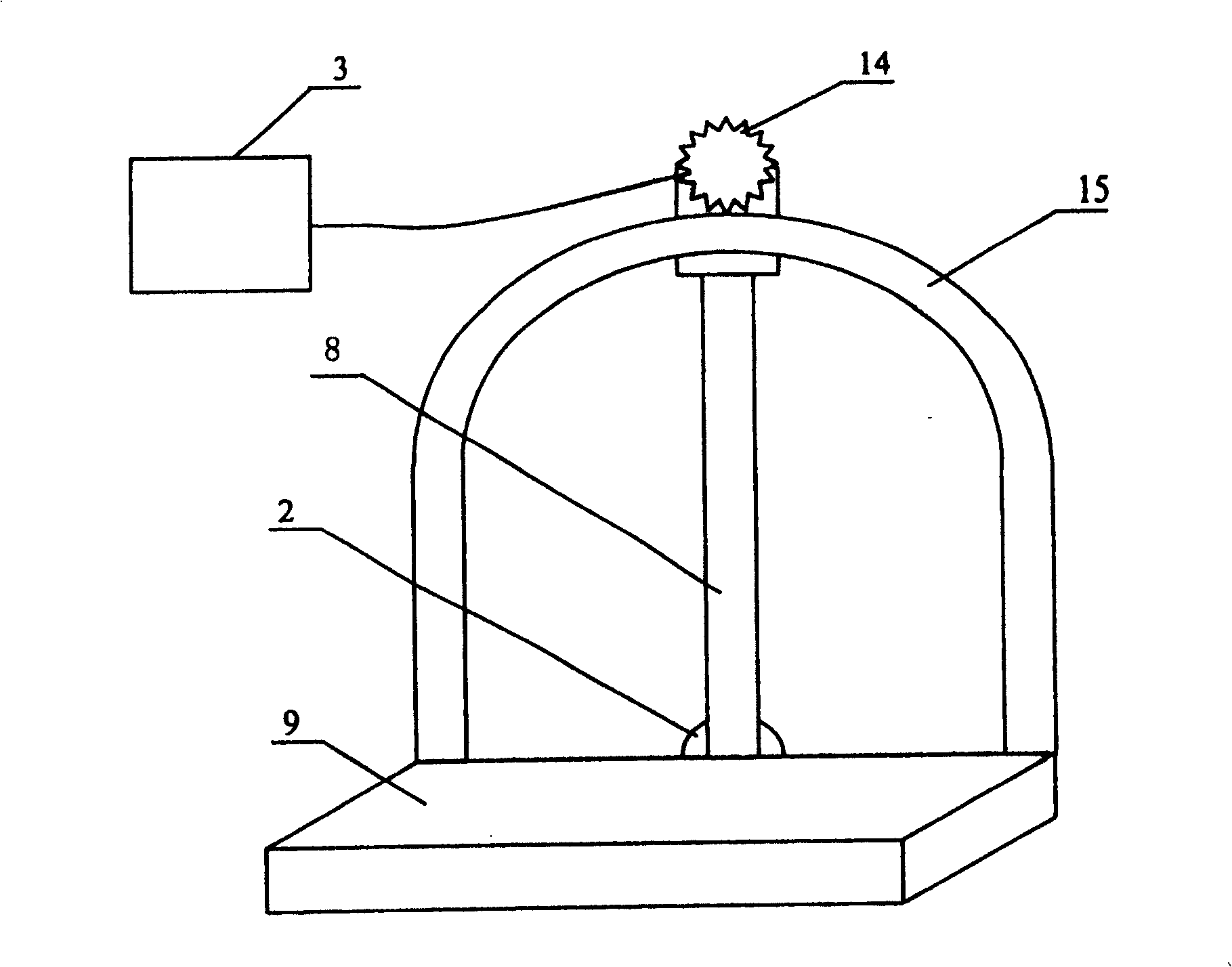
[0043] The structure of the imaging bracket is as follows: the positioning screw 2 is fixed on the base 9,...


PUM


Abstract

The present invention discloses a fluorescence optic imaging device. It includes light closed box, excitation light source, imaging module, imaging support and control portion. The excitation light source is used for producing excitation light to excite laser; the imaging module includes imaging detector and florescence filter, the fluorescence filter is placed in the front of imaging detector. Besides, said invention also provides the concrete structure of the imaging support, and the control portion includes a central controller and a multi-angle imaging controller. Besides, said invention also provides its working principle and its operation method.

Description

technical field [0001] The invention relates to an optical imaging device, in particular to a device for exciting the fluorescence of substances from multiple directions and performing optical imaging on the fluorescence of substances from multiple angles. Background technique [0002] Some substances can absorb and store energy from the outside (such as light energy, chemical energy, etc.) Called fluorescence, this process of using external energy to obtain fluorescence is the excitation of fluorescence. The fluorescence characteristics of different substances will be different. Using the fluorescence characteristics of the substance, it can be used to analyze the composition of the substance, or it can be used as a tracer to mark other objects, and then track the behavior of the marked substance. Fluorescence optical imaging is optical imaging of the fluorescence of objects, which can be used to acquire fluorescence images in various applications such as biology, medicine...

Claims


Application Information

Patent Timeline
Patent Type & Authority Patents(China)
IPC IPC(8): G01N21/64G01N21/84
Inventor 骆清铭曾绍群陈延平刘谦张智红
Owner HUAZHONG UNIV OF SCI & TECH
Learn More