
Field effect transistor structure, associated semiconductor storage cell, and corresponding production method

A field-effect transistor and memory cell technology, applied in semiconductor/solid-state device manufacturing, transistors, semiconductor devices, etc., can solve problems such as the influence of memory time, the increase of effective threshold voltage leakage current, and the charging effect caused by high-impedance well connections. Simplifies precise alignment and avoids the effect of body effects

Inactive Publication Date: 2008-10-01
INFINEON TECH AG
View PDF5 Cites 0 Cited by
  • Summary
  • Abstract
  • Description
  • Claims
  • Application Information

AI Technical Summary

Problems solved by technology

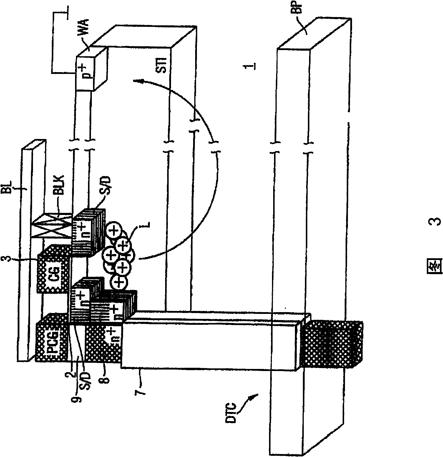
[0016] However, a deficiency of the body or the semiconductor substrate directly adjacent to the field effect transistor or its high-impedance well connection will sooner or later have a charging effect and will thus reduce the effective threshold voltage and thus the leakage current due to the body effect Therefore, it increases; especially in the example of the DRAM semiconductor memory unit shown in Figure 3, its memory time (retention time) will be affected accordingly

Method used


Image

  • Field effect transistor structure, associated semiconductor storage cell, and corresponding production method
  • Field effect transistor structure, associated semiconductor storage cell, and corresponding production method
  • Field effect transistor structure, associated semiconductor storage cell, and corresponding production method

Examples


Embodiment Construction

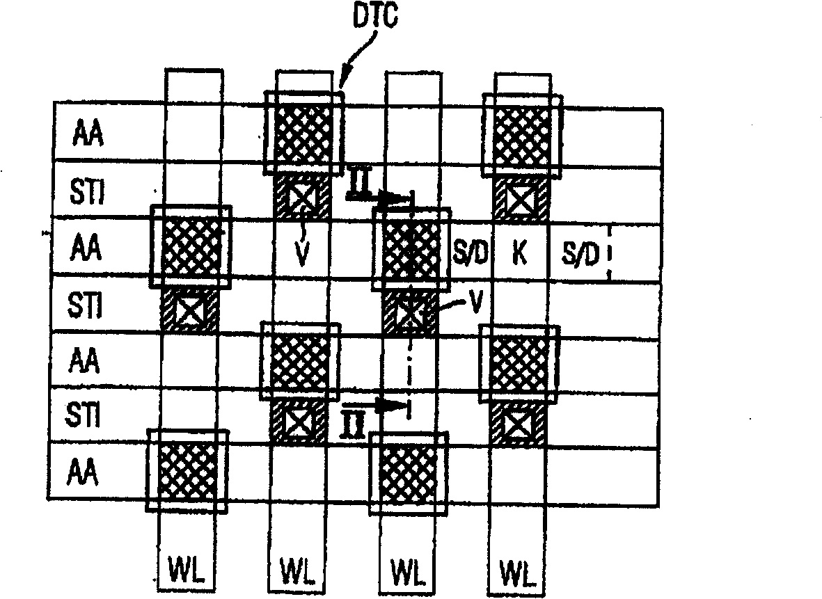
[0041] figure 2 According to the first specific embodiment of the present invention, a schematic plan view of a semiconductor storage unit device is briefly described; wherein and figure 1 The same component symbols represent the same or corresponding components and film layers, and will not be repeated here.

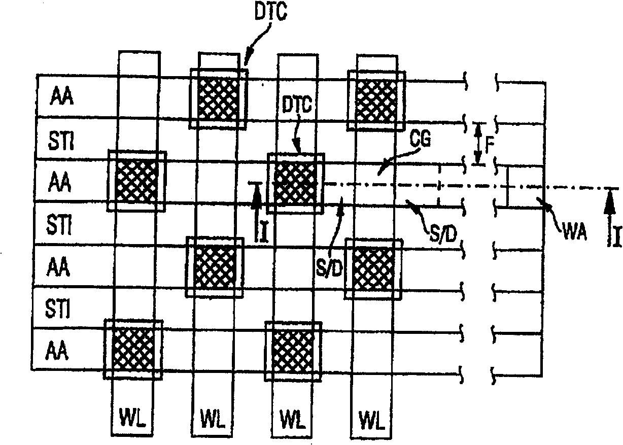
[0042] In this example, Figure 3 illustrates the along figure 1 The section of the intercept line I-I is essentially the same as figure 2 A corresponding cross-section (not shown) in is the same; however, the well connection doped region WA is not required in specific embodiments of the present invention.

[0043] according to figure 2 , using a groove V to replace the well connection doped region, which is generally required and not beneficial when the packaging density is increased, the groove V is formed in a shallow trench insulation STI, and one of the semiconductor substrates A diode doped region is formed at its bottom region.

[0044] Figure 5 is along t...


PUM


Abstract

The invention relates to a field effect transistor structure, an associated semiconductor storage cell, and a corresponding production method. A diode-doping area (4) within a semiconductor substrate (1) is embodied with a field effect transistor structure (S / D, 3, K) while an electrically conducting diode-connecting layer (5) connects a control layer (3) of the field effect transistor structure to the diode-doping area (4) so as to create a diode (D), whereby excess charge carriers (L) in the semiconductor substrate (1) can be eliminated such that an undesired body effect is prevented.

Description

technical field [0001] The present invention relates to a field effect transistor structure, a related semiconductor storage unit and its related manufacturing method, and in particular to a field effect transistor structure that can be used in dynamic random access (DRAM) memory. Background technique [0002] In semiconductor technology, so-called dynamic random access memories (DRAM) are produced in particular using state-of-the-art technology with the highest integration density; however, with increasing packaging density or integration density, the following difficulties arise in DRAM semiconductor memories: [0003] In order to control the short channel behavior (roll-off, roll-off) of the selection transistor in the DRAM semiconductor memory unit, in all production technologies, it is necessary to increase the related well doping (welldoping) or channel implantation (channel implant); However, this method will generate high body effect and damage the writing behavior o...

Claims


Application Information

Patent Timeline
IPC IPC(8): H01L27/02H01L27/102H01L29/10H01L21/336H01L21/8242H01L27/108H01L29/78
CPCH01L27/0214H01L27/108H01L27/10844H01L27/1087H01L27/1082H10B12/00H10B12/33H10B12/01H10B12/0387
Inventor M·希尔勒曼恩R·斯特拉斯塞
Owner INFINEON TECH AG
Learn More