Double communication area electronic non-parking charging lane system and method f realizing same thereof

An electronic non-stop, dual-communication technology, applied in instruments, ticketing equipment, etc., can solve problems such as difficulty in reversing, ETC lane congestion, and low traffic speed, to avoid reversing or wrong release, ensure traffic speed, and enhance processing capabilities. Effect

Active Publication Date: 2008-09-24
GUANGZHOU HUAGONG INFORMATION SOFTWARE
View PDF6 Cites 0 Cited by
  • Summary
  • Abstract
  • Description
  • Claims
  • Application Information

AI Technical Summary

Problems solved by technology

[0008] (2) The traffic speed of the ETC system vehicles in the short communication area is low: the communication area is about 1 to 6.5 meters in front of the automatic railing. traffic efficiency
[0009] (3) There is a communication blind spot near the automatic railing: In the existing lane layout, the antenna is located about 2 meters in front of the railing. Due to the directional characteristics of the antenna and OBU, the OBU cannot communicate normally when it reaches the bottom of the antenna.
Therefore, there is a communication blind area of ​​about 2 meters or more in front of the railing. When the vehicle does not complete the transaction in the communication area and drives in front of the automatic railing, the transaction cannot continue, which affects the traffic of the vehicle
[0010] (4) The situation of reversing is serious: Due to the performance difference of OBU and the complexity of vehicle driving behavior, the situation of reversing the vehicle frequently occurs in practical applications
When the traffic is heavy, it is very difficult to reverse the car, which may easily cause the ETC lane to be blocked
[0011] (5) The phenomenon of malicious bypass queue jumping and escaping fees cannot be solved: in operation, malicious bypass queue jumping phenomenon is common, that is, the vehicle stays at the gap between the ETC and the adjacent lane, when the automatic railing of the ETC lane is lifted , quickly inserted into the ETC lane to pass first, to achieve the purpose of evading fees
Since the gap in the isolation zone is used to guide vehicles that cannot trade normally to leave the ETC lane, it cannot be closed, so it is impossible to effectively prevent this phenomenon of malicious queue jumping and fee evasion
[0012] The Chinese invention patent with the patent number ZL9712589.X provides "a method of automatic toll collection without parking". This method uses two different antennas (fan beam antenna, full beam antenna) The signal is compared with the received signal from outside the communication area to identify the vehicle. Although the recognition accuracy of this scheme is improved compared with the scheme using a single fan beam antenna, it still belongs to the short communication area ETC system in essence and still has the aforementioned defects.

Method used


Image

  • Double communication area electronic non-parking charging lane system and method f realizing same thereof
  • Double communication area electronic non-parking charging lane system and method f realizing same thereof
  • Double communication area electronic non-parking charging lane system and method f realizing same thereof

Examples


Embodiment 1

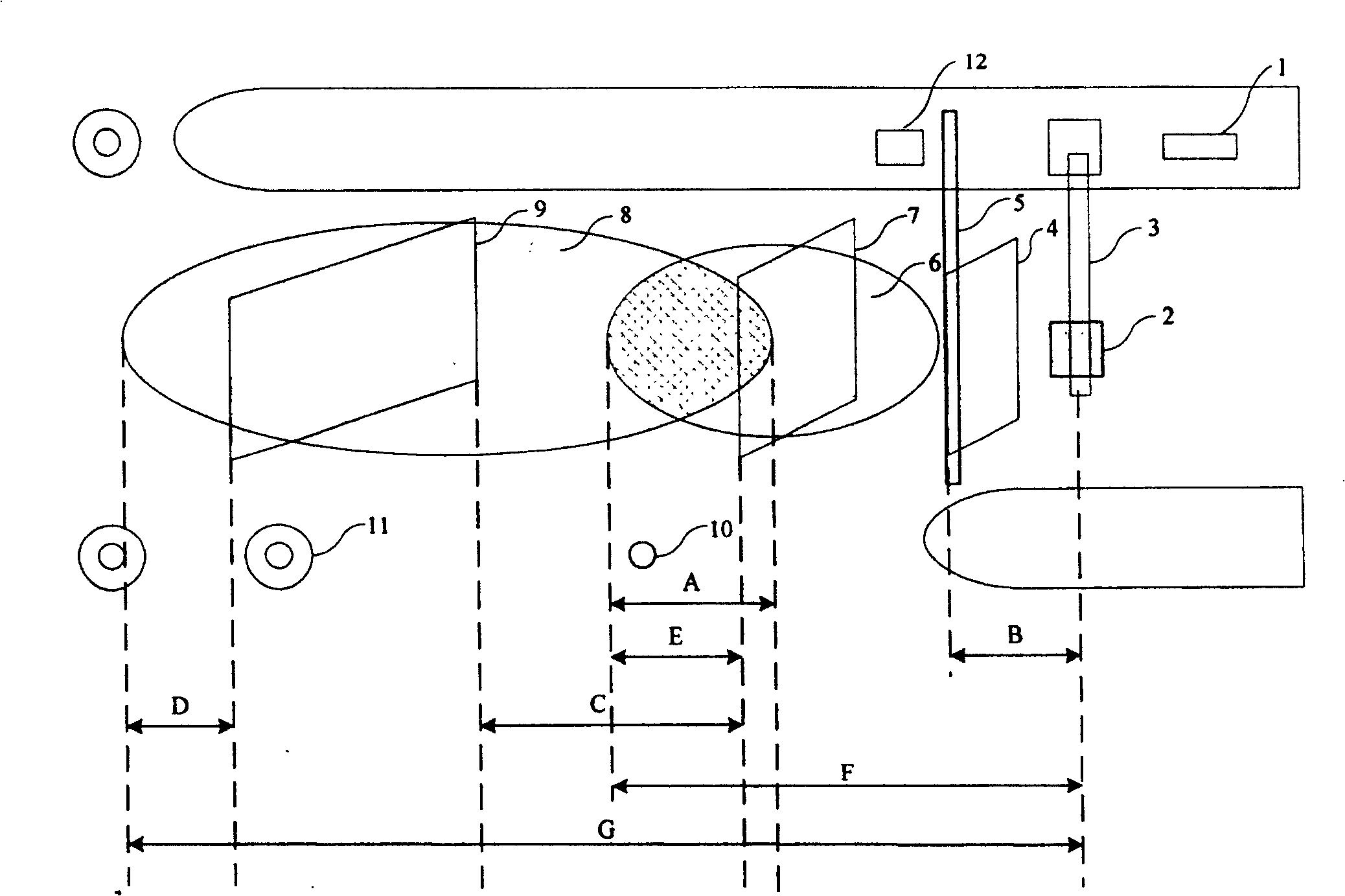
[0041] The specific structure of the present invention is as Figure 1 ~ Figure 3 shown by figure 1 It can be seen that the dual-communication area electronic non-stop toll lane system includes a main control machine 1, an antenna 2, an automatic railing 5, a trigger ground sense 9, a snapping ground sense 7, a pole drop ground sense 4, a fee display 12, an antenna 2, The automatic railing 5, the trigger ground sense 9, the snap ground sense 7, the pole drop ground sense 4, and the fee display 12 are respectively connected to the main control machine 1, the antenna 2 is installed on the gantry 3 and is located above the driveway, and the antenna 2 is in the driveway The communication coverage areas above are respectively the far communication area 8 and the near communication area 6. The far communication area 8 and the near communication area 6 partially overlap, and the length A of the overlapping area is 1.5m. The distance B behind the gantry 3 behind the railing is 1.5m; ...

Embodiment 2

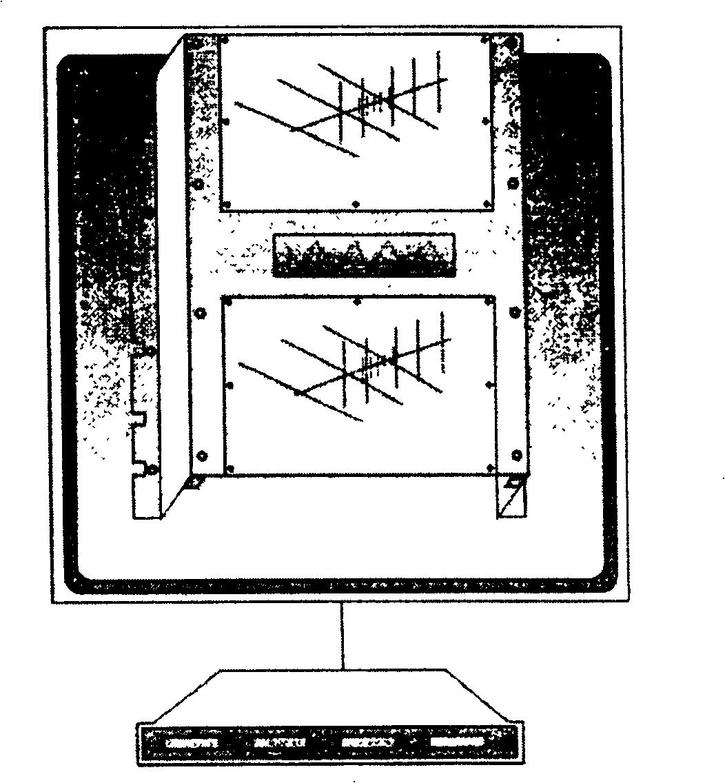
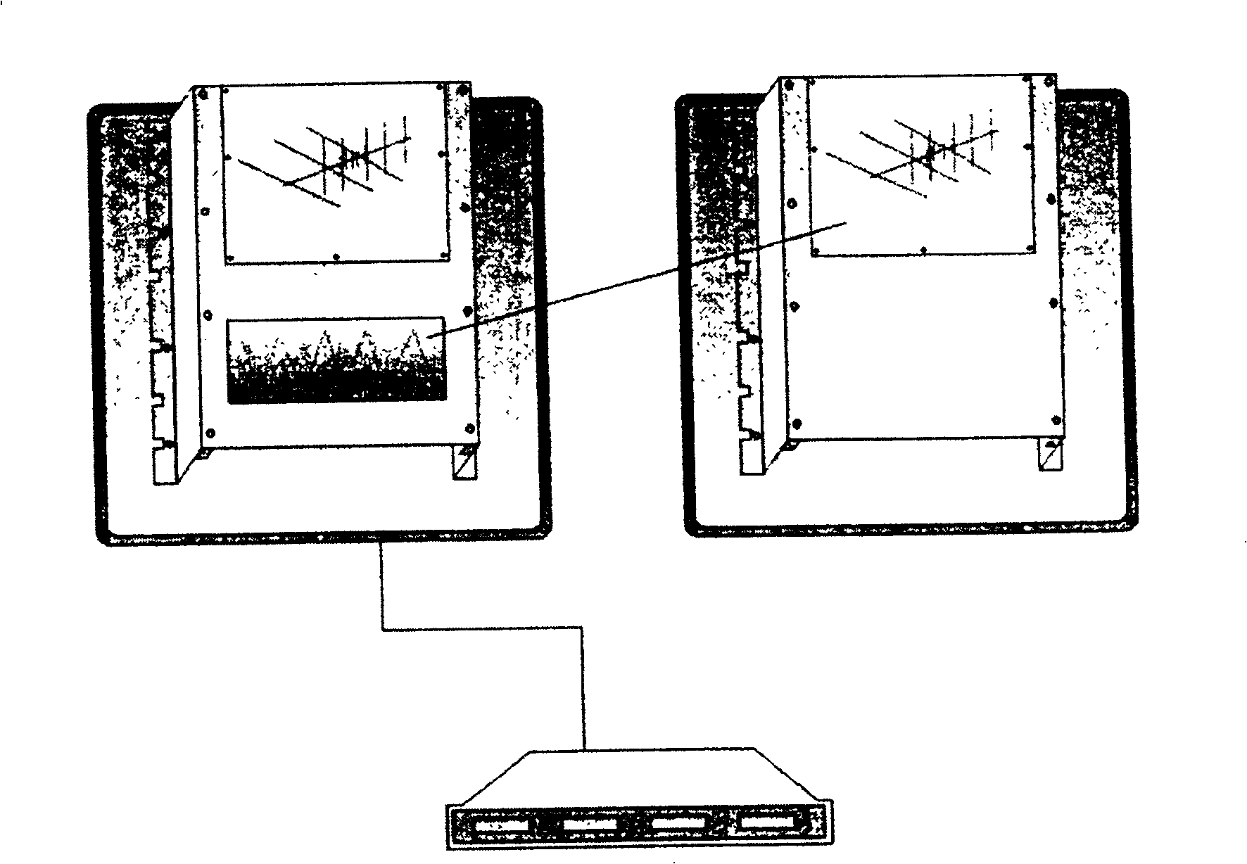
[0048] This embodiment is the same as Embodiment 1 except the following features: the structure of the antenna is as follows image 3 As shown, two groups of wireless communication devices are set separately and located in two antenna boxes respectively. The logic processing circuit is arranged in one of the antenna boxes and connected to the wireless communication device in the antenna box, and the logic processing circuit is connected to the wireless communication device in the other antenna box through a connection line.


PUM


Abstract

The invention provides a double-communication region electronic nonstop fees- charging roadway system, comprising master control machine, antenna, auto railing, trigger ground sensor, snapping ground sensor, railing drop ground sensor, and fees number display, where the antenna comprises two groups of wireless communication devices with different emitting angles, interconnected through logic processing circuit, and is installed on a gantry and above the roadway, where the far and near communication areas covered by the two groups of wireless communication devices are overlapped. A double-communication region electronic nonstop fees-charging roadway method switches between communication areas according to the position of the vehicle and the trade state under the control of a roadway system, so as to let the normally trading vehicles pass or hold up the illegal vehicles. The invention can solve the vehicle following interference problem and assure the vehicle traffic speed; eliminate the communication blind areas in front of the auto railing to strengthen the ability to process abnormal conditions; reduce the vehicle following interference caused by vehicle backing and stop escaping fees; prevent viciously jumping the queue from the side road; and assure the vehicles that have traded normally pass.

Description

technical field [0001] The invention relates to an electronic non-stop toll lane system, in particular to an electronic non-stop toll lane system with dual communication areas and a realization method thereof. Background technique [0002] At present, in the electronic toll collection (ETC) lane system, the vehicle conducts microwave communication with the antenna through the on-board unit (OBU) in a single communication area (after the communication area is activated, the size and position of the communication area cannot be changed) to complete the electronic non-stop charging. Parking fee transactions. According to the size of the communication area, the existing ETC lane system can be divided into two types: long communication area ETC system and short communication area ETC system. The ETC transaction logic is as follows: [0003] (1) Locking: In order to serialize the OBU transaction and prevent the influence of the following vehicle OBU, the lane system needs to lock...

Claims


Application Information

Patent Timeline
Patent Type & Authority Patents(China)
IPC IPC(8): G07B15/00G07B15/06
Inventor 李坚徐晓帆饶辉范崇贵张伟民
Owner GUANGZHOU HUAGONG INFORMATION SOFTWARE
Why Eureka
Try Eureka