Radio frequency smart card computer lock
A radio frequency smart card and computer lock technology, applied in the field of daily necessities, can solve the problems of restricting the popularization and promotion of locks, high maintenance costs, and too much influence
- Summary
- Abstract
- Description
- Claims
- Application Information
AI Technical Summary
Problems solved by technology
Method used
Image
Examples
example 1
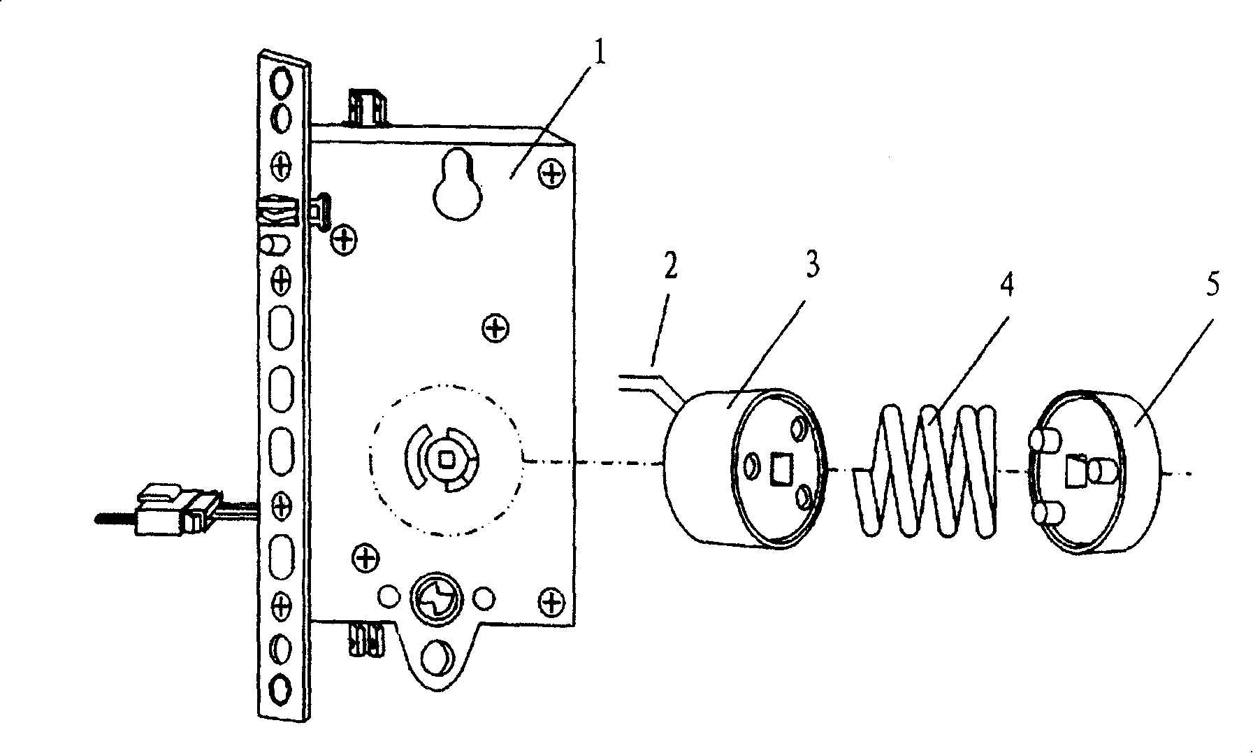
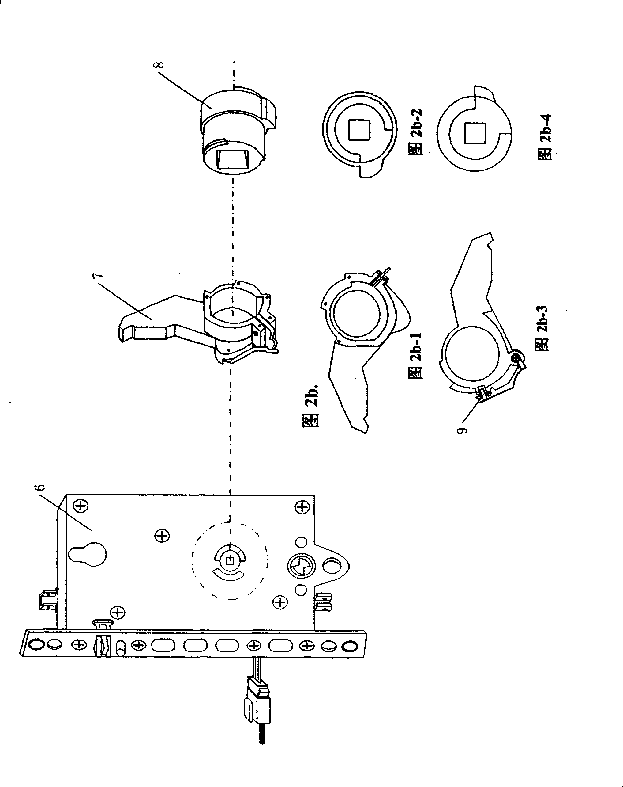
[0064] against Figure 2a , Figure 2b, Figure 2c The specific structure, its working process is briefly described as follows:
[0065] Figure 2a . The clutch control part of the lock body 1 of the electromagnetic clutch lock shown includes an electromagnetic coil 3 , a clutch spring 4 and a soft magnet 5 . Under normal conditions, the electromagnetic clutch is in a disengaged state, and the transmission mechanism does not work; when working, the coil lead 2 is input with excitation, resulting in 4 compression, and the electromagnetic coil 3 and the soft magnet 5 are engaged. At this time, the transmission mechanism plays a role, and the lock can be opened by turning the lock handle. After the input excitation of the coil lead wire 2 disappears, the electromagnetic coil 3 and the soft magnet 5 are separated, and the lock cannot be opened.
[0066] 2b and 2b-1, 2b-2, 2b-3 and 2b-4, the clutch control part of the lock body 6 of the electronically controlled mechanical clutch...
example 2
[0073] combine Figure 4 Figure 6 shows a specific implementation method of the RF identification and control system. The central processing module of the identification and control system includes Y21, Y22, IC27, and IC29; the transmitting and receiving module of the identification and control system includes RX21, IC21, IC26, IC25, TX21, and BG31; the sound and photoelectric status prompt module and status indication module include IC24, BG21, D21, D22, R22, R23; internal opening / key is S22; identification code learning key is XUE21; identification code memory module includes BG30, IC28, R36; control and status monitoring and delay self-locking module includes BG22, BG23, BG24, BG25, BG26, BG27, BG28, L21, IC29; battery power supply module includes BT21, IC22, IC23; external close key position S23; touch sensor switch is CHU21, R31, R32, R33, R34, BG29. The following describes the working process of the RF identification and control system under various trigger conditions. ...
PUM
 Abstract
Description
Claims
Application Information
 - R&D
- Intellectual Property
- Life Sciences
- Materials
- Tech Scout
- Unparalleled Data Quality
- Higher Quality Content
- 60% Fewer Hallucinations
Browse by: Latest US Patents, China's latest patents, Technical Efficacy Thesaurus, Application Domain, Technology Topic, Popular Technical Reports.
© 2025 PatSnap. All rights reserved.Legal|Privacy policy|Modern Slavery Act Transparency Statement|Sitemap|About US| Contact US: help@patsnap.com


