
Closed type solid lock cylinder and lock

A closed, solid-state technology, applied in the field of anti-theft, can solve the problem of poor security of the lock cylinder and achieve the effect of security protection

Inactive Publication Date: 2014-07-16
邓建春
View PDF3 Cites 0 Cited by
  • Summary
  • Abstract
  • Description
  • Claims
  • Application Information

AI Technical Summary

Problems solved by technology

[0003] The existing lock core has poor safety due to its inherent structural defects, that is, the lock core is unlocked by inserting a key and turning the key to drive the shaft of the lock hole to rotate.

Method used


Image

  • Closed type solid lock cylinder and lock
  • Closed type solid lock cylinder and lock
  • Closed type solid lock cylinder and lock

Examples


Embodiment 1

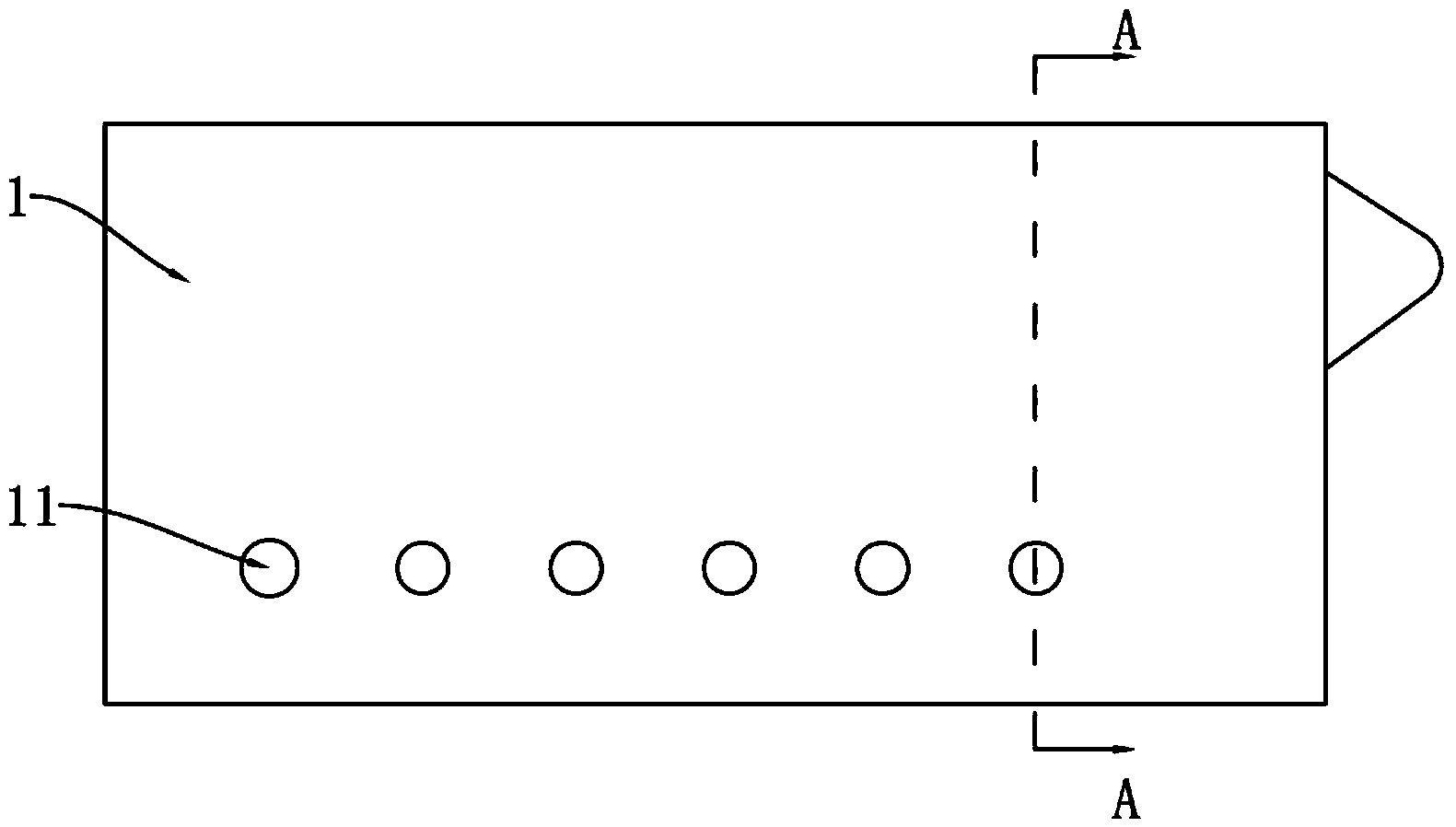
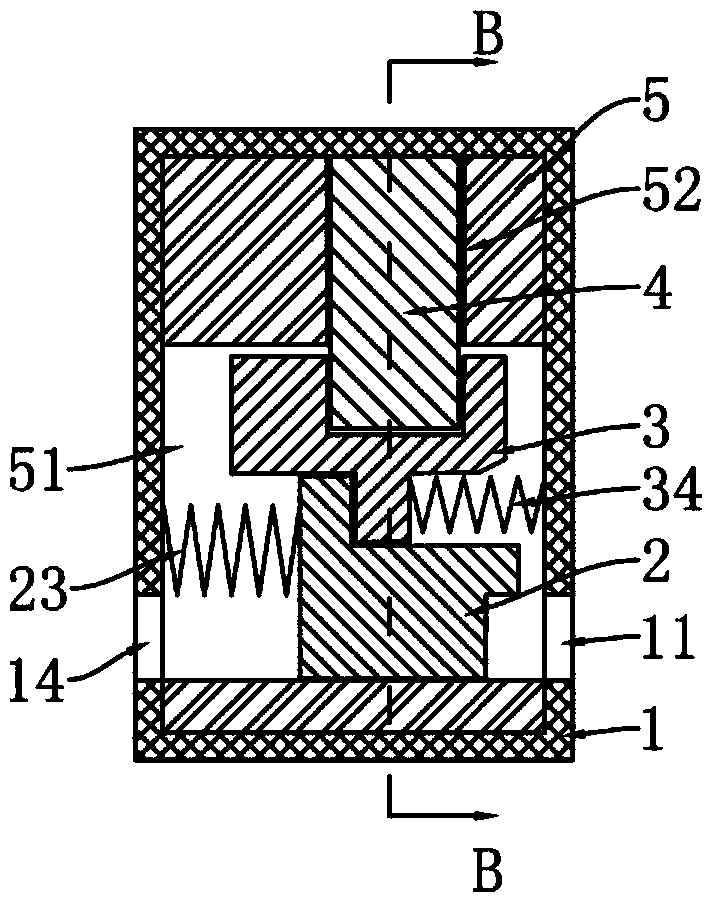
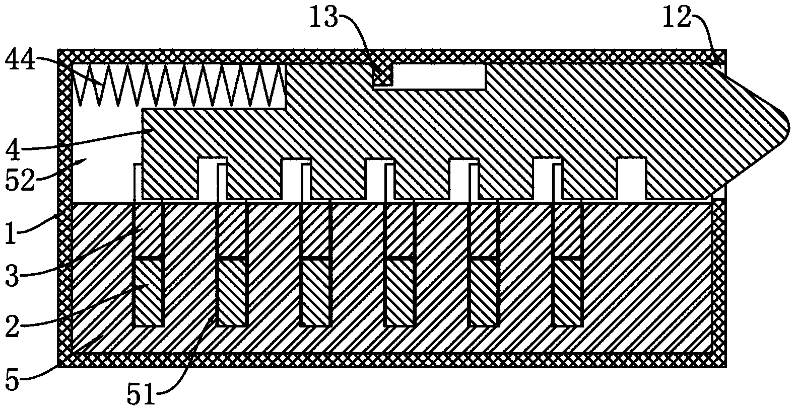
[0033] see Figure 1 to Figure 6 . The closed solid body lock cylinder described in this embodiment is composed of a housing 1 , an unlocking piece 2 , a locking piece 3 , a locking tongue 4 , a base 5 and elastic components.

[0034] The housing 1 is a rectangular parallelepiped, hollow, with a plurality of first keyholes 11 disposed on its front, and a bolt exit hole 12 disposed on one side thereof. A plurality of first keyholes 11 are evenly arranged in a row. In this embodiment, six first keyholes 11 are provided. Of course, other different numbers can also be set. Theoretically speaking, according to this embodiment For the structure of the lock cylinder, the more the number of the first key holes, the higher the safety performance of the lock cylinder.

[0035] The base 5 is provided with a plurality of locking plate sliding grooves 51 and a locking tongue sliding groove 52 , and the locking plate sliding grooves 51 and the locking tongue sliding grooves 52 are partial...

Embodiment 2

[0045] see Figure 7. The basic structure of the lock described in this embodiment is basically the same as that of the lock cylinder described in Embodiment 1, and only the differences will be described below.

[0046] The difference from Embodiment 1 is that the outer end of the lock tongue 4 is set as a vertical apex 43b instead of a horizontal apex; the vertical apex 43b is like a vertically placed prism. The longitudinal apex 43 b comprises two vertical faces extending compared to a line lying on the plane of symmetry of the bolt 4 .

[0047] For the convenience of unlocking on both sides of the door, corresponding to the first keyhole 11, six second keyholes 14 are provided on the back side of the housing 1, and the second keyhole 14 and the first keyhole 11 are on two sides. on the opposite side.

[0048] In order to more clearly illustrate the working mode of the lock core or lock in the above two embodiments, the following description will be made in conjunction wi...


PUM


Abstract

The invention discloses a closed type solid lock cylinder and a lock. The closed type solid lock cylinder comprises a shell and a base fixed to the shell. A plurality of first key holes and a spring bolt outlet are formed in the shell. A plurality of locking plate chutes and a spring bolt chute are formed in the base and partially arranged in an interacting mode. Unlocking plates and locking plates are arranged in the locking plate chutes. A spring bolt is arranged in the spring bolt chute. Each locking plate is located between the corresponding unlocking plate and the spring bolt. A groove opening enabling the spring bolt to pass through is formed in each locking plate. A through groove enabling each locking plate to pass through is formed in the spring bolt. A first elastic component is arranged between each unlocking plate and the inner wall of the shell. A second elastic component is installed between each locking plate and the inner wall of the shell. A third elastic component is installed between the spring bolt and the inner wall of the shell. The closed type solid lock cylinder solves the problems that an existing lock cylinder scale is prone to unlocking and damage, the mutual-opening rate is high, the design structure is complex, and cost is high; the lock cylinder can serve as a completely-concealed lock cylinder and safer protection is achieved with the combination of other transmission structures.

Description

technical field [0001] The invention belongs to the field of anti-theft, and relates to a mechanical anti-theft device, in particular to a lock cylinder and a lock. Background technique [0002] Now the marbles and blade lock cylinders that are available on the market usually need to insert a key in the lockhole, and the lock can be opened when the key is turned under normal conditions. The lock core of this lock is provided with a rotatable lock hole shaft and a non-rotatable lock core seat. One side of the lock hole is provided with one or more rows of marbles. In the locked state, the lock column is stuck between the lock core seat and the lock hole shaft under the elastic force of the spring. When the key is inserted into the lock hole, the concave and convex parts on the key press the pin, and the pin pushes the lock cylinder, and the lock cylinder presses the spring and completely retreats into the lock cylinder seat. At this time, the lock shaft can rotate with the k...

Claims


Application Information

Patent Timeline
Patent Type & Authority Applications(China)
IPC IPC(8): E05B15/00E05B15/10E05B19/00E05B27/00E05B9/00
Inventor 邓建春
Owner 邓建春
Learn More