
Method and system for equipment switching in communication system

A communication system and equipment technology, applied in the field of switching technology, can solve the problems of large impact on the system, lack of transparency and flexibility, large switching operation delay, etc., to improve switching speed and reliability, and improve efficiency. and flexibility, the effect of improving the switching speed

Inactive Publication Date: 2008-06-18
HUAWEI TECH CO LTD
View PDF2 Cites 0 Cited by
  • Summary
  • Abstract
  • Description
  • Claims
  • Application Information

AI Technical Summary

Problems solved by technology

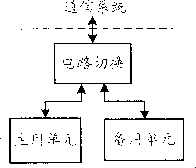
[0009] It can be seen that the switching technology used in the current communication system, because the active / standby arbitration and switching notification are directly performed by the underlying hardware, the upper layer application modules and service modules are in a passive state, which is not conducive to high-level equipment maintenance; and because the switching is directly performed by the Circuit switching is implemented, so it is not transparent to the upper layer application, and the switching has a great impact on the system; again, the switching process is completed mechanically by the circuit, which is inflexible and cannot support automatic manual switching; in general, when the equipment is switched It also requires data transfer, reconfiguration of backup equipment, etc., and requires a long delay, which makes it far from meeting the requirements of real-time business and high service quality in the telecommunications network
[0010] In practical application, the above scheme has the following problems: Since the device switching is initiated and executed by the underlying hardware, the upper-layer application is in a passive processing state, which does not support the maintenance of high-level devices; Configuration takes a lot of time, so the switching operation has a long delay and cannot meet real-time requirements; because the switching is realized through physical address conversion or circuit switching, it does not have transparency and flexibility, so it has a great impact on the entire communication system

Method used


Image

  • Method and system for equipment switching in communication system
  • Method and system for equipment switching in communication system
  • Method and system for equipment switching in communication system

Examples


Embodiment Construction

[0047] In order to make the object, technical solution and advantages of the present invention clearer, the present invention will be further described in detail below in conjunction with the accompanying drawings.

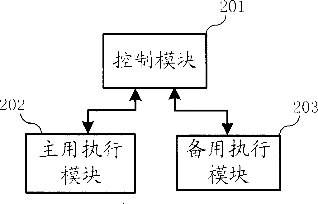
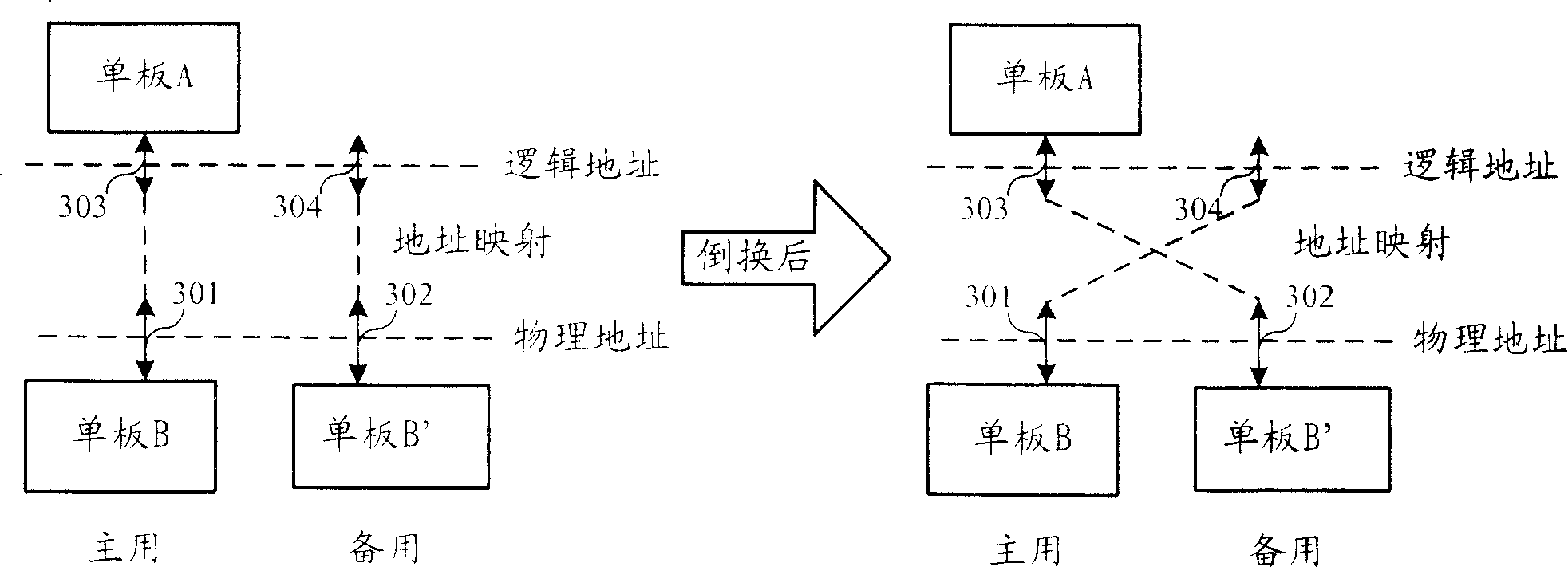
[0048] The invention adopts a step-by-step process under control to complete the switching process, logically divides the entire switching operation into multiple sub-steps, and improves the flexibility of the switching operation. The execution function and the control function are separated and realized by the execution module and the control module respectively. The transparency of the switching operation is realized by using the mapping of the logical address and the physical address, and the impact of the switching on the entire communication system is minimized. The data warm backup mechanism is adopted to maintain the synchronization between the main and standby units, and to improve the speed of performing the main and standby switchover. The business smoo...


PUM


Abstract

This invention discloses a switching method of communication equipment, in addition to a system. It separates the switch controlling function and executive function through dividing controlling module and master and stand-by operation module; the switching flow process comprises several executive steps and conditions, which realize switch flow process controlling and condition migration; it uses the logical address and physics address mapping mechanism to realize the transparent switching of the substratum communication channel; it has the back-up data before and after switching, and has the business smooth dealing mechanism and back-up mode of the master and stand-by veneer; and when happen abnormal thing in switching process, it can realize the switching recovery.

Description

technical field [0001] The invention relates to communication technology, in particular to switching technology in communication equipment. Background technique [0002] Telecommunications networks are required to provide reliable and uninterrupted services to their users, especially in some important business applications, such as electronic money, order processing, customer service, inventory management, e-mail and Internet access, etc., business survivability becomes more important than ever, with availability requirements of 99.999% and beyond. Therefore, the network survivability has become an important factor affecting network design and construction, and the equipment used in the telecommunication network also needs to have high reliability accordingly. [0003] In communication systems, redundant backup and load sharing are commonly used methods to enhance equipment reliability. Redundant backup refers to the use of multiple devices with the same function for repla...

Claims


Application Information

Patent Timeline
IPC IPC(8): H04B1/74
CPCH04L12/403H04L49/552H04L12/40176
Inventor 吕朝霞谈伟
Owner HUAWEI TECH CO LTD
Learn More