
Universal cementing plug

a plug and plug technology, applied in the field of cementing plugs, can solve the problems of affecting increasing the cost of manufacturing, and normal pressure rise at the surface, so as to increase the wiping efficiency of the wipers on the plugs, increase the wiping efficiency, and increase the surface contact

Inactive Publication Date: 2010-08-17
HALLIBURTON ENERGY SERVICES INC
View PDF36 Cites 3 Cited by
  • Summary
  • Abstract
  • Description
  • Claims
  • Application Information

AI Technical Summary

Benefits of technology

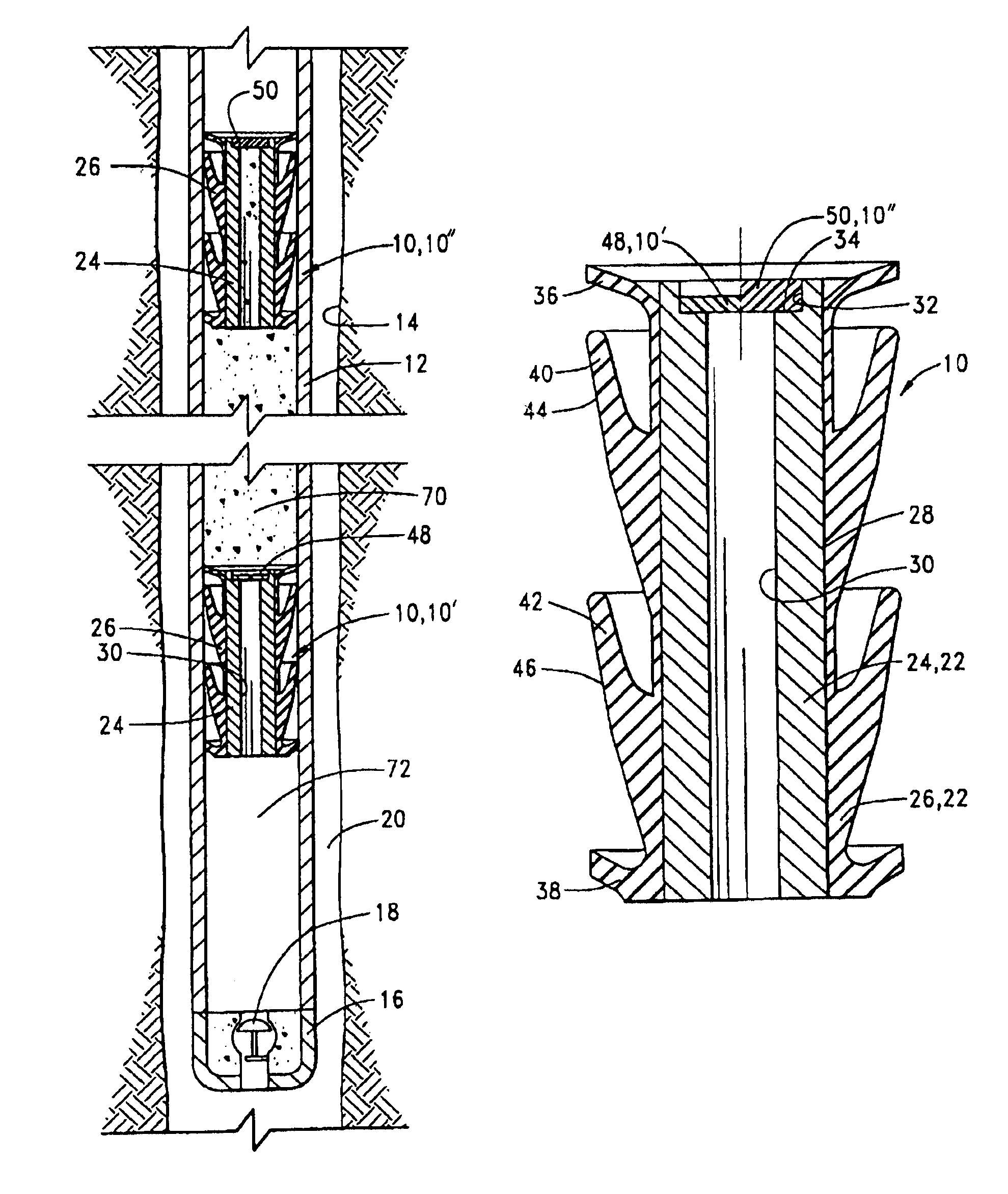
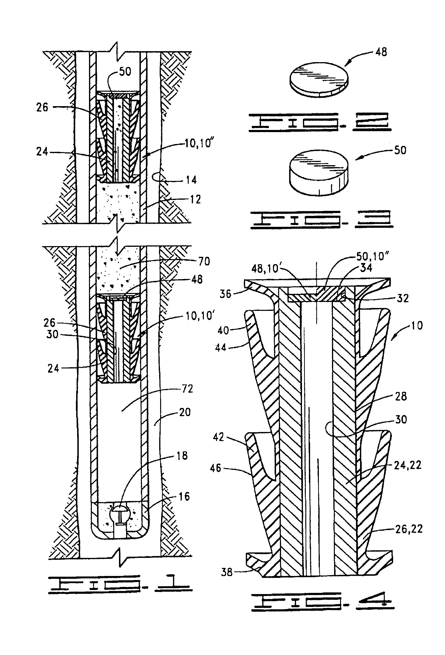
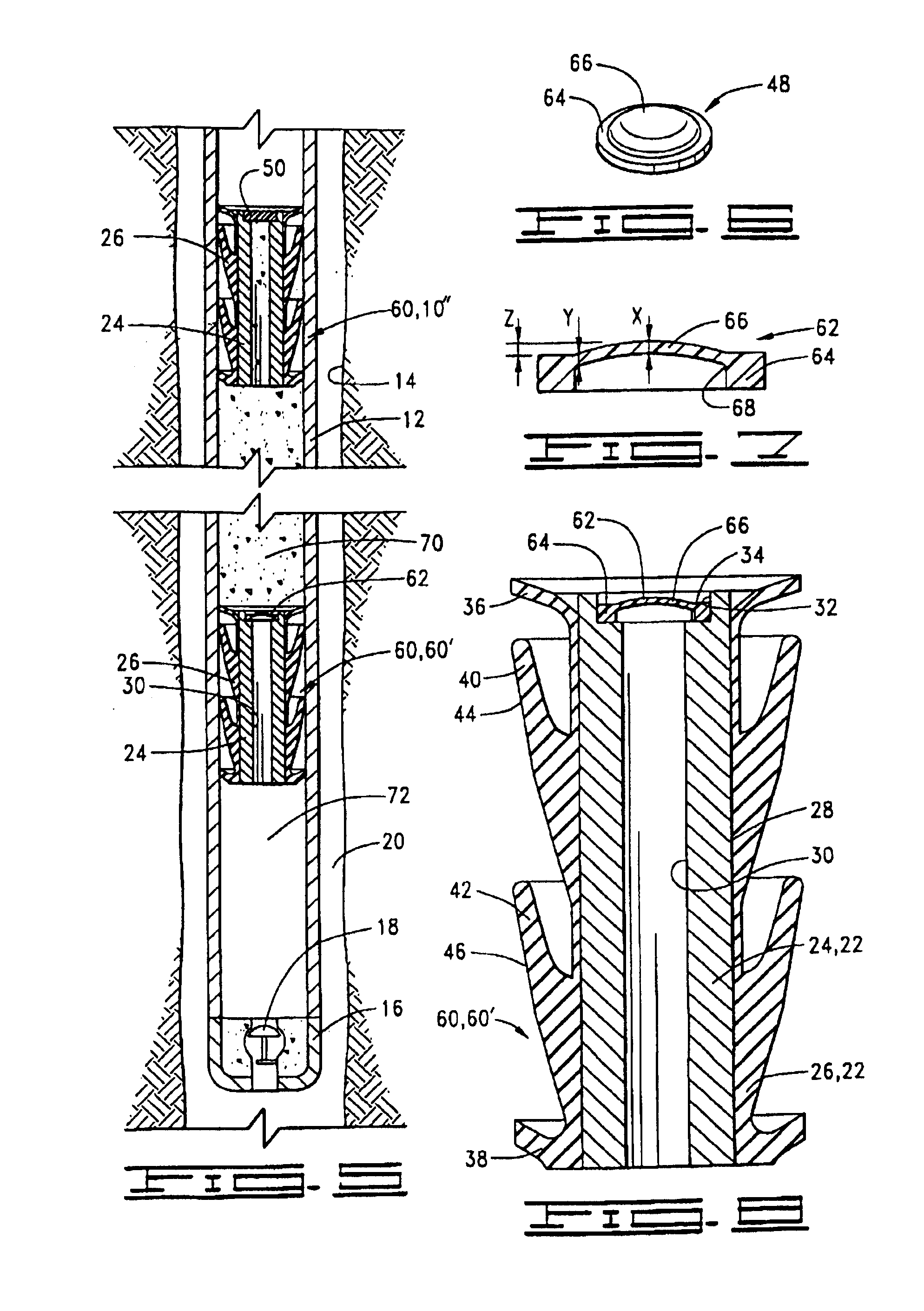
[0010]Another advantage of the present invention is that the shearable member may be interchangeable with a plurality of shearable members, including, but not limited to, the two embodiments previously described, designed to shear at any one of a selected number of differential pressures as necessary for different well conditions. This is an improvement over the previous design which had essentially one shear pressure.
[0011]With prior art cementing plugs, the wiping efficiency of the wipers on the plugs is affected by pumping rate and wear along the casing surface. The cementing plug of the present invention provides an improved wiper design which offers more surface contact, and as the plug is pumped down the casing, wiping efficiency is increased. As a top cup on the plug wears, the pressure is transferred to a bottom cup which prolongs the surface engagement maintaining the wiping, resulting in extended wear.SUMMARY OF THE INVENTION
[0012]The present invention is a universal cementing plug which may be configured as either a bottom cementing plug or a top cementing plug. The plug may also be described as an improved wiping and / or extended wear plug.
[0013]The cementing plug is adapted for use in cementing casing in a well and comprises a body member defining a central opening therethrough, an elastomeric jacket disposed around the body member and having a wiper cup extending therefrom for engaging an inner surface of the casing, and an insert disposed across the central opening in the body member for at least temporary closure thereof. The insert is one of a plurality of interchangeable inserts. These inserts include a shearable insert or disk adapted for shearing and thereby opening the central opening when a predetermined differential pressure is applied across the shearable insert and a substantially non-shearable insert or disk adapted for substantially permanent closure of the central opening. When the cementing plug is configured as a bottom plug, a shearable insert is used, and when the cementing plug is configured as a top plug, a non-shearable insert is used.
[0014]Each body member defines a recess adjacent to the central opening with an upwardly facing shoulder therein. When configuring the cementing plug as a bottom plug or a top plug, one of the inserts is disposed on the shoulder.
[0015]The invention may also be described as a cementing plug for use in cementing casing in a well, comprising a body member and an elastomeric jacket disposed around the body member with a wiper cup having a substantially conical outer surface thereon extending upwardly and outwardly at an acute angle with respect to a longitudinal axis of the plug. The conical surface deflects into substantially cylindrical, wiping engagement with an inner surface of the casing when the plug is disposed therein. This provides a large wiping surface for improved wiping and increased wear. Preferably, the wiper cup is one of a plurality of such wiper cups. As the upper wiper cup wears, the pressure will be gradually applied to the next lower wiper cup which continues the wiping action. This also provides extended wear life.

Problems solved by technology

This causes a normal pressure rise at the surface and notifies the operator that the cementing job is complete.
Because each plug requires different construction, separate molds must be used for each of the plugs which increase the costs of manufacturing, and also, the two separate plugs must be kept in inventory.
With prior art cementing plugs, the wiping efficiency of the wipers on the plugs is affected by pumping rate and wear along the casing surface.
As a top cup on the plug wears, the pressure is transferred to a bottom cup which prolongs the surface engagement maintaining the wiping, resulting in extended wear.

Method used


Image

  • Universal cementing plug
  • Universal cementing plug
  • Universal cementing plug

Examples


examples

[0044]Although various materials may be used for shearable insert 62, a preferred material is 23570 glass-filled plastic from Baelow-Hunt, Inc., of Tulsa, Okla. This material has a working temperature range of room temperature to about 410° F.

[0045]The following table illustrates the pressure at which domed portion 66 shears based on different values of X and Y using this material.

[0046]

XYShear Pressure0.100°0.125°370psi0.125°0.150°700psi0.131°-0.135°0.175°1200psi

[0047]In a preferred embodiment, but not by way of limitation, the height Z of domed portion 66 above ring portion 64 is approximately equal to center thickness X of domed portion 66.

[0048]Second embodiment shearable material 62 may be positioned on shoulder 34 in body member 24 of plug subassembly 22 to form second embodiment bottom plug 60′, as seen in FIGS. 5 and 8.

[0049]In second embodiment cementing plug 60, top plug 10″ used with bottom plug 60′ is identical to that in first embodiment cementing plug 10.


PUM


Abstract

A cementing plug having a universal construction and improved wiping and extended wear characteristics. The cementing plug has a plug subassembly with a body member and an elastomeric jacket on the body member. The body member defines a central opening therethrough with a shoulder therein. To configure the plug as a bottom cementing plug, a shearable insert is positioned on the shoulder, and to configure the plug as a top cementing plug, a non-shearable insert is positioned on the shoulder. The shearable insert is one of a plurality of such inserts designed to shear at correspondingly different shear pressures. In a first embodiment, the shearable insert is a substantially flat disk having a uniform thickness, and in a second embodiment, the shearable insert has an outer ring portion and a relatively thin inner domed portion. Thus, a bottom plug may be pumped down a well casing with cement and a top plug thereabove so that when the bottom plug lands at the bottom of the casing, the shearable insert will shear at the predetermined pressure. The jacket has one or more wiper cups which have a conical surface extending at an acute angle with respect to a longitudinal axis of the plug, thereby providing a substantially large contact area in the well casing to improve wiping efficiency and extend life.

Description

CROSS REFERENCE[0001]This application is a continuation of U.S. patent application Ser. No. 09 / 970,432 filed Oct. 3, 2001 which is a reissue of U.S. patent application Ser. No. 09 / 175,664 filed Oct. 20, 1998, now U.S. Pat. No. 6,196,311 which issued on Mar. 6, 2001. This application is related to U.S. patent application Ser. No. 10 / 307,113 filed Apr. 10, 2003(now abandoned) and U.S. patent application Ser. No. 11 / 267,892 filed Nov. 4, 2005 both of which are divisional of U.S. patent application Ser. No. 09 / 970,432 filed Oct. 3, 2001. <?insert-end id="INS-S-00001" ?>BACKGROUND OF THE INVENTION[0002]1. Field of the Invention[0003]This invention relates to cementing plugs for use in cementing casing in a well, and more particularly, to a universal cementing plug having improved wiping and extended wear and which includes a plurality of interchangeable inserts so that the plug may be selectively used as a top or a bottom plug.[0004]2. Description of the Prior Art[0005]In the proce...

Claims


Application Information

Patent Timeline
Patent Type & Authority Patents(United States)
IPC IPC(8): E21B33/16E21B33/05
CPCE21B33/05E21B33/16
Inventor TREECE, HAROLD O.
Owner HALLIBURTON ENERGY SERVICES INC
Learn More