
Rate loop processor for perceptual encoder/decoder

a perceptual encoder and loop processor technology, applied in the field of signal processing, can solve the problems of affecting the quality of audio signals, so as to achieve enhanced compression, detect and avoid binaural artifacts, and improve audio quality. the effect of quality

Inactive Publication Date: 2006-04-25
LUCENT TECH INC
View PDF59 Cites 94 Cited by
  • Summary
  • Abstract
  • Description
  • Claims
  • Application Information

AI Technical Summary

Benefits of technology

[0014]An illustrative embodiment of the present invention employs a filter bank architecture using a Modified Discrete Cosine Transform (MDCT). In order to code the full range of signals that may be presented to the system, the illustrative embodiment advantageously uses both L / R (Left and Right) and M / S (Sum / Difference) coding, switched in both frequency and time in a signal dependent fashion. A new stereophonic noise masking model advantageously detects and avoids binaural artifacts in the coded stereophonic signal. Interchannel redundancy is exploited to provide enhanced compression for without degrading audio quality.
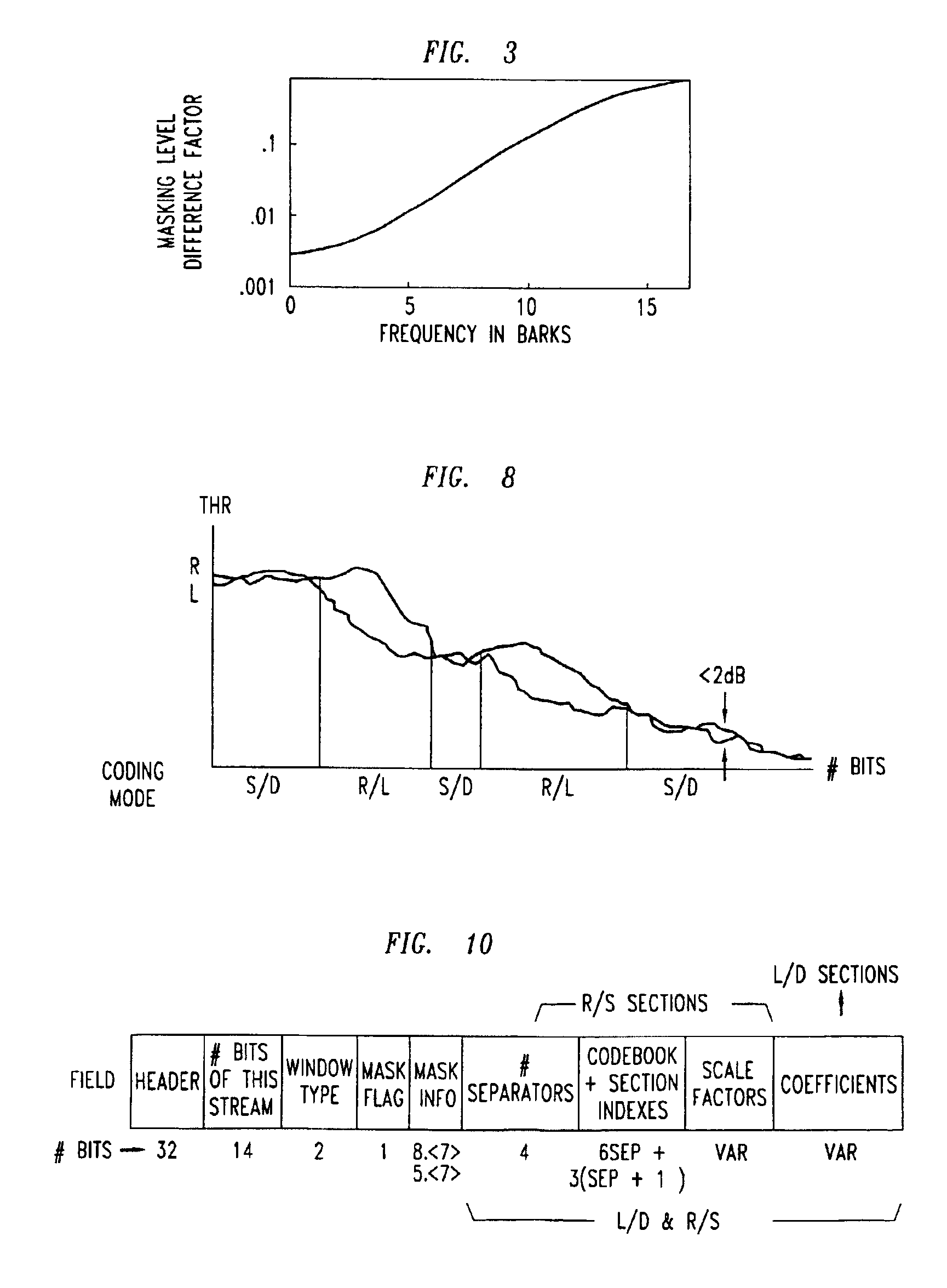
[0015]The time behavior of both Right and Left audio channels is advantageously accurately monitored and the results used to control the temporal resolution of the coding process. Thus, in one aspect, an illustrative embodiment of the present invention, provides processing of input signals to terms of either a normal MDCT window, or, when signal conditions indicate, shorter windows. Further, dynamic switching between RIGHT / LEFT or SUM / DIFFERENCE coding modes is provided both in time and frequency to control unwanted binaural noise localization, to prevent the need for overcoding of SUM / DIFFERENCE signals, and to maximize the global coding gain.
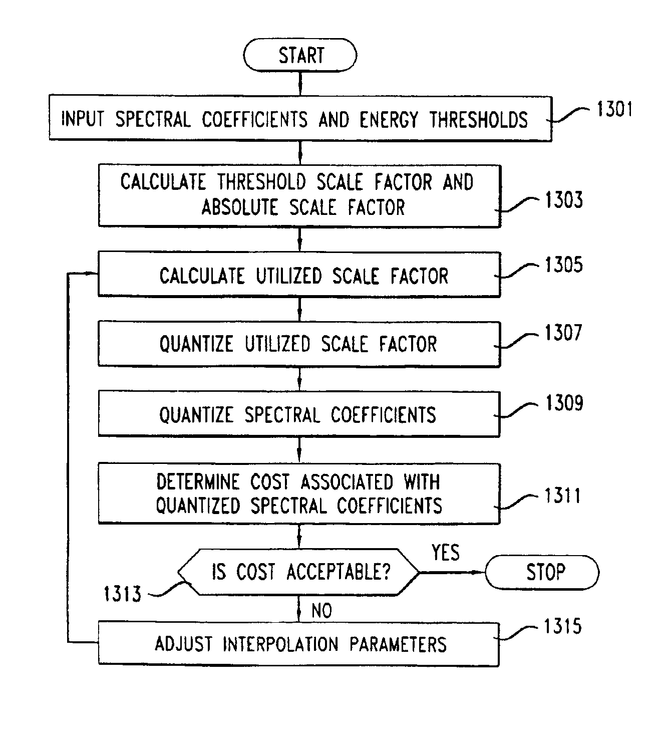
[0016]A typical bitstream definition and rate control loop are described which provide useful flexibility in forming the coder output. Interchannel irrelevancies, are advantageously eliminated and stereophonic noise masking improved, thereby to achieved improved reproduced audio quality in jointly coded stereophonic pairs. The rate control method used in an illustrative embodiment uses an interpolation between absolute threshold and masking threshold for signals below the rate-limit of the coder, and a threshold elevation strategy under rate-limited conditions.
[0017]In accordance with an overall coder / decoder system aspect of the present invention, it provides advantageously to employ an improved Huffman-like entropy coder / decoder to further reduce the channel bit rate requirements, or storage capacity for storage applications. The noiseless compression method illustratively used employs Huffman coding along with a frequency-partitioning scheme to efficiently code the frequency samples for L,R,M and S, as may be dictated by the perceptual threshold.
[0018]The present invention provides a mechanism for determining the scale factors to be used in quantizing the audio signal (i.e., the MDCT coefficients output from the analysis filter bank) by using an approach different from the prior art, and while avoiding many of the restriction and costs of prior quantizer / rate-loops. The audio signals quantized pursuant to the present invention introduce less noise and encode into fewer bits than the prior art.

Problems solved by technology

While these emerging digital techniques are capable of producing high quality signals, such performance is often achieved only at the expense of considerable data storage capacity or transmission bandwidth.
This is especially important when coding stereophonic audio information where coded information corresponding to one stereo channel, when decoded for reproduction, can interfere or interact with coding information corresponding to the other stereo channel.
It has been found that the independent coding of the two channels of a stereo pair, especially at low bit-rates, can lead to a number of undesirable psychoacoustic artifacts.
However, such additional SNR constraints typically require the expenditure of additional channel capacity or (in storage applications) the use of additional storage capacity, at low frequencies, while also degrading the monophonic performance of the coding.

Method used


Image

  • Rate loop processor for perceptual encoder/decoder
  • Rate loop processor for perceptual encoder/decoder
  • Rate loop processor for perceptual encoder/decoder

Examples


Embodiment Construction

1. Overview

[0034]To simplify the present disclosure, the following patents, patent applications and publications are hereby incorporated by reference in the present disclosure as if fully set forth herein: U.S. Pat. No. 5,040,217, issued Aug. 13, 1991 by K. Brandenburg et al, U.S. patent application Ser. No. 07 / 292,598, entitled Perceptual Coding of Audio Signals, filed Dec. 30, 1988; J. D. Johnston, Transform Coding of Audio Signals Using Perceptual Noise Criteria, IEEE Journal on Selected Areas in Communications, Vol. 6, No. 2 February 1988); International Patent Application (PCT) WO 88 / 01811, filed Mar. 10, 1988; U.S. patent application Ser. No. 07 / 491,373, entitled Hybrid Perceptual Coding, filed Mar. 9, 1990, Brandenburg et al, Aspec: Adaptive Spectral Entropy Coding of High Quality Music Signals, AES 90th Convention (1991); Johnston, J., Estimation of Perceptual Entropy Using Noise Masking Criteria, ICASSP, (1988); J. D. Johnston, Perceptual Transform Coding of Wideband Stereo...


PUM


Abstract

A method and apparatus for quantizing audio signals is disclosed which advantageously produces a quantized audio signal which can be encoded within an acceptable range. Advantageously, the quantizer uses a scale factor which is interpolated between a threshold based on the calculated threshold of hearing at a given frequency and the absolute threshold of hearing at the same frequency.

Description

[0001]This is a reissue application of U.S. Pat. No. 5,627,938 filed Sep. 22, 1994 as application Ser. No. 08 / 310,898 which is a continuation of application Ser. No. 07 / 844,811, filed on Mar. 2, 1992, now abandoned, which is a continuation-in-part of application Ser. No. 07 / 844,967 filed Feb. 28, 1992, now abandoned, which is a continuation of Ser. No. 07 / 292,598 filed Dec. 30, 1988 now abandoned<?insert-end id="INS-S-00003" ?>.CROSS-REFERENCE TO RELATED APPLICATIONS AND MATERIALS[0002]The following U.S. patent applications filed concurrently with the present application and assigned to the assignee of the present application are related to the present application and each is hereby incorporated herein as if set forth in its entirety: “A METHOD AND APPARATUS FOR THE PERCEPTUAL CODING OF AUDIO SIGNALS,” by A. Ferreira and J. D. Johnston, application Ser. No. 07 / 844,819, now abandoned, which in turn was parent of application Ser. No. 08 / 334,889, allowed Jul. 11, 1996: “A METHOD ...

Claims


Application Information

Patent Timeline
Patent Type & Authority Patents(United States)
IPC IPC(8): G10L19/02G10L21/04G10L19/00G10L19/035G10L25/00H03M1/12H03M7/30H03M7/36H03M7/40H04B1/66
CPCH04B1/665G11B20/10
Inventor JOHNSTON, JAMES DAVID
Owner LUCENT TECH INC
Learn More