
Method and circuit for detecting a fault in a clock signal for microprocessor electronic devices including memory elements

a clock signal and microprocessor technology, applied in the field of circuits for detecting irregularities in clock signals of electronic devices, can solve problems such as malfunctions during normal use, unusable effects of devices, and failure to correctly reset new devices

Inactive Publication Date: 2003-06-24
STMICROELECTRONICS SRL
View PDF12 Cites 6 Cited by
  • Summary
  • Abstract
  • Description
  • Claims
  • Application Information

AI Technical Summary

Benefits of technology

The solution idea underlying the present invention is to monitor the clock signal applied to the device and, if an irregularity is detected, generate a

Problems solved by technology

However if the FLASH EEPROM is integrated on a microprocessor device or if it contains inside itself a microprocessor for management of the reading, programming and erasure phases it may happen that following occurrence of an irregular situation such as failure of the clock signal, some outputs of the microprocessor are found with random logic levels.
This can cause undesired effects in the device such as e.g. programming of one of the UPROM registers and irreversible corruption of the contents thereof.
Such malfunctions can occur during normal use of the microcontroller or memory or following incorrect use thereof, e.g. when the correct timings for the signals applied to its inputs are not respected.
However it may happen that in irregular situations such as e.g. if the device is replaced by another without turning off power to the card the-external capacitor remains charged and the new device is not correctly reset.
There can thus occur irregular situations in the microprocessor which can lead e.g. to writing of one of the UPROM registers and irreversible corruption of its contents.

Method used


Image

  • Method and circuit for detecting a fault in a clock signal for microprocessor electronic devices including memory elements
  • Method and circuit for detecting a fault in a clock signal for microprocessor electronic devices including memory elements
  • Method and circuit for detecting a fault in a clock signal for microprocessor electronic devices including memory elements

Examples


Embodiment Construction

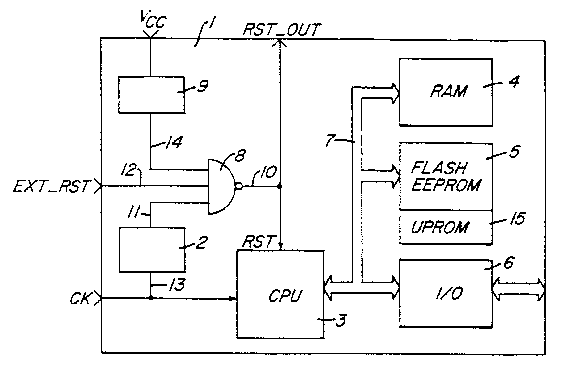
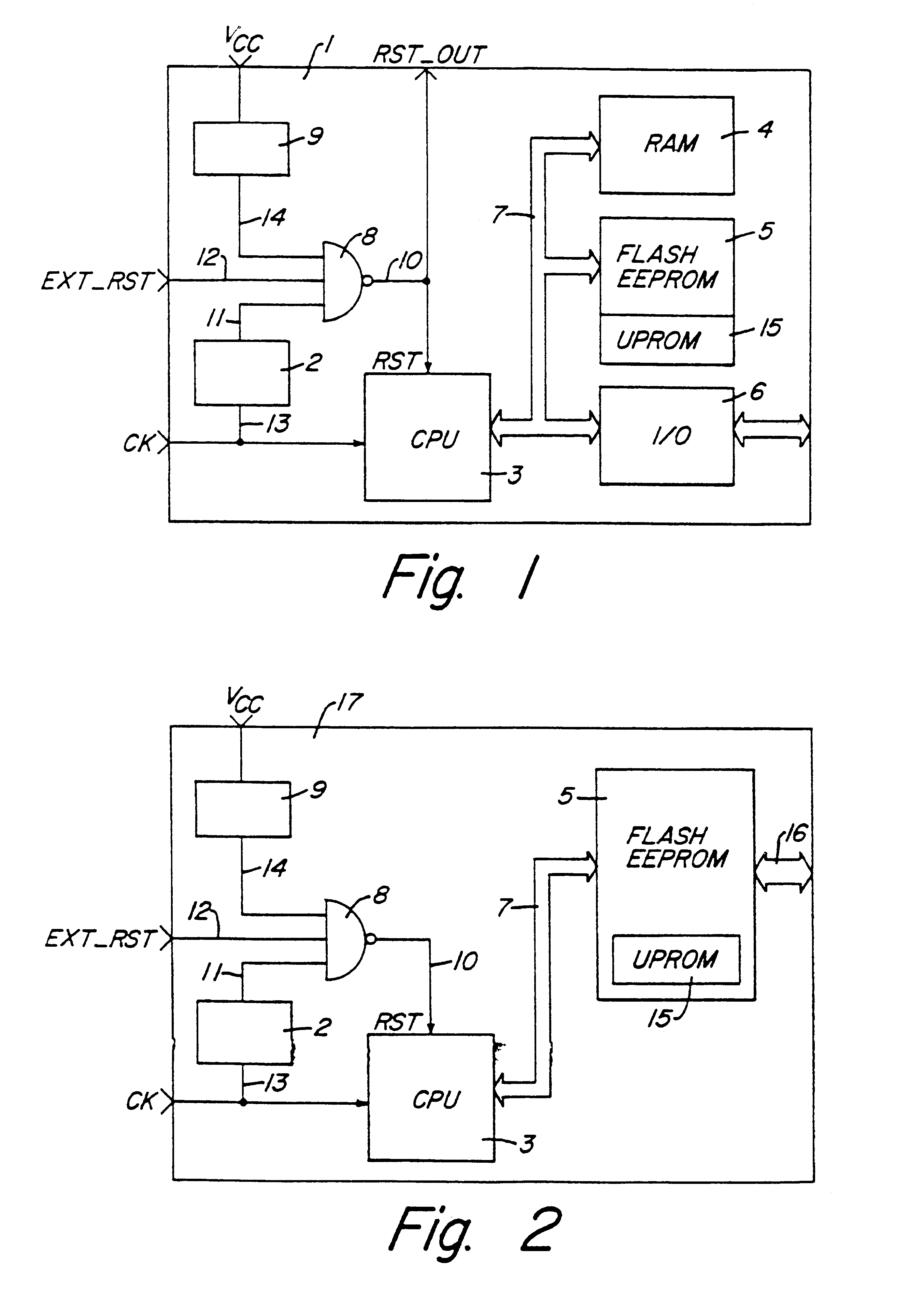
With reference to the figures reference number 1 indicates as a whole and schematically a first electronic device while said microcontroller comprises in a single semiconductor chip a microprocessor 3, a non-volatile memory matrix 5, a volatile memory matrix (RAM) 4, input and output ports 6 and some circuit blocks 2, 8 and 9 designed to generate a reset signal.

Blocks 3, 4, 5 and 6 communicate with each other through a group of electrical connections 7 known as data and address busses with which they are interfaced.

The non-volatile memory matrix 5 is electrically programmable and erasable and can be the EEPROM or the FLASH EEPROM type and is used for permanently memorizing the sequence of instructions for the microprocessor 3. This memory contains a certain number of cells of UPROM (Unerasable and Programmable Read Only Memory) 15 which is programmed by the manufacturer of the integrated circuit during testing of the device and subsequently is not visible to the user.

The volatile me...


PUM


Abstract

An electronic device including a microprocessor, a circuit generating a clock signal, and memories of both the volatile type and the non-volatile type, incorporates a circuit for generation of a reset signal capable of detecting a stop in the oscillation of said clock signal and generating a logic signal coupled with the reset input of the microprocessor. The circuit monitors the clock signal applied to the device and, if an irregularity is detected, generate a reset signal holding the microprocessor in a safe state. The reset signal is held until the circuit generating the clock signal resumes normal operation.

Description

CROSS REFERENCE TO RELATED APPLICATIONThe present application is related to U.S. patent application Ser. No. 08 / 414,919 entitled "CIRCUIT FOR DETECTING A FAULT IN A CLOCK SIGNAL FOR MICROPROCESSOR ELECTRONIC DEVICES" filed of even date herewith by the inventors hereof and assigned to the assignee herein, and incorporated by reference herein.BACKGROUND OF THE INVENTION1. Field of the InventionThe present invention relates to a circuit for detecting irregularities in a clock signal of electronic devices containing a microprocessor and non-volatile memory elements.The present invention concerns specifically two types of electronic device, to wit: microcontrollers containing EEPROM or FLASH EEPROM non-volatile memories, and FLASH EEPROM memories using internally a microprocessor for management of the reading, programming and erasing phases.The following description is given with reference to this field of application only for the purpose of simplifying discussion thereof.2. Description ...

Claims


Application Information

Patent Timeline
IPC IPC(8): H03K5/19G06F11/30G06F1/04G06F1/24G06F11/00G06F11/07
CPCG06F1/04G06F1/24G06F11/073G06F11/0754G06F11/0757G06F11/0793G06F11/0796H03K5/19
Inventor MORONI, ANGELOSCARRA, FLAVIOTADDEO, ALBERTO
Owner STMICROELECTRONICS SRL
Learn More