
Refresh oscillator

a technology of oscillator and oscillator, which is applied in the direction of oscillator generator, digital storage, instruments, etc., can solve problems such as operation problems, and achieve the effect of stabilizing the initial operation of the biasing circui

Inactive Publication Date: 2005-06-16
SK HYNIX INC
View PDF7 Cites 3 Cited by
  • Summary
  • Abstract
  • Description
  • Claims
  • Application Information

AI Technical Summary

Benefits of technology

[0012] Another object of the present invention is to provide a refresh oscillator which can always generate a constant period of signals even in a low power supply voltage.

Problems solved by technology

The resulting levels of the biases change the oscillation period, which causes problems in the operation.

Method used


Image

  • Refresh oscillator
  • Refresh oscillator
  • Refresh oscillator

Examples


Embodiment Construction

[0018] A refresh oscillator in accordance with a preferred embodiment of the present invention will now be described in detail with reference to the accompanying drawings.

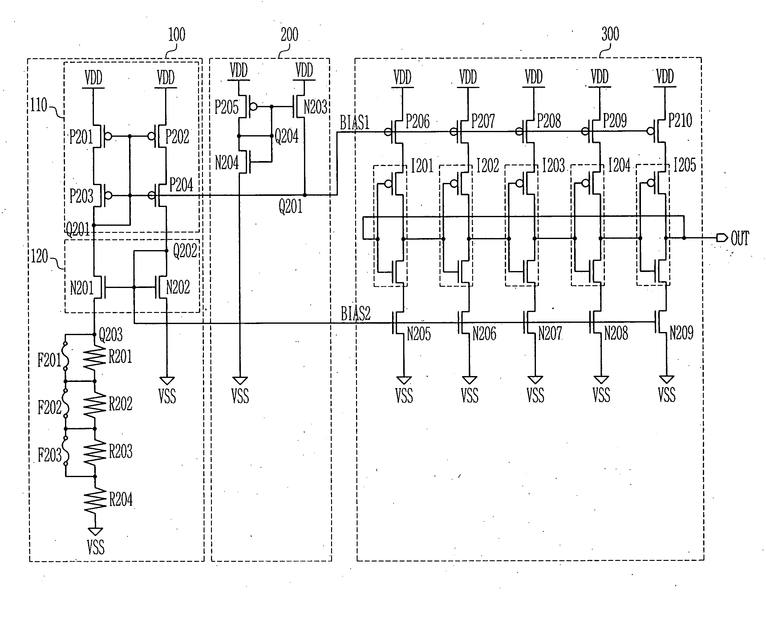
[0019]FIG. 2 is a circuit diagram illustrating the refresh oscillator in accordance with the present invention.

[0020] A biasing circuit 100 includes first and second current mirrors 110 and 120, and determines levels of first and second biases BIAS1 and BIAS2. The first current mirror 110 includes four diode connected PMOS transistors P201 to P204, therefore, the four PMOS transistors P201 to 204 are operated in saturation region if a voltage between a drain and a source of each PMOS transistor P201 to P204 is higher than a threshold voltage.

[0021] The second current mirror 120 includes first and second NMOS transistors N201 and N202 that are operated in a saturation region. Accordingly, the first and second biases BIAS1 and BIASI2 maintain a constant level regardless of variations of a power supply voltage VDD....


PUM


Abstract

The present invention discloses a refresh oscillator including a biasing circuit for generating constant first and second biases by using current mirrors, regardless of variations of a power supply voltage, a start-up circuit for stabilizing the initial operation of the biasing circuit by applying a predetermined level of potential to the biasing circuit, and an oscillator for generating a constant period of refresh signals according to the first and second biases. The refresh oscillator can improve operation reliability by generating a constant period of signals, regardless of variations of the power supply voltage.

Description

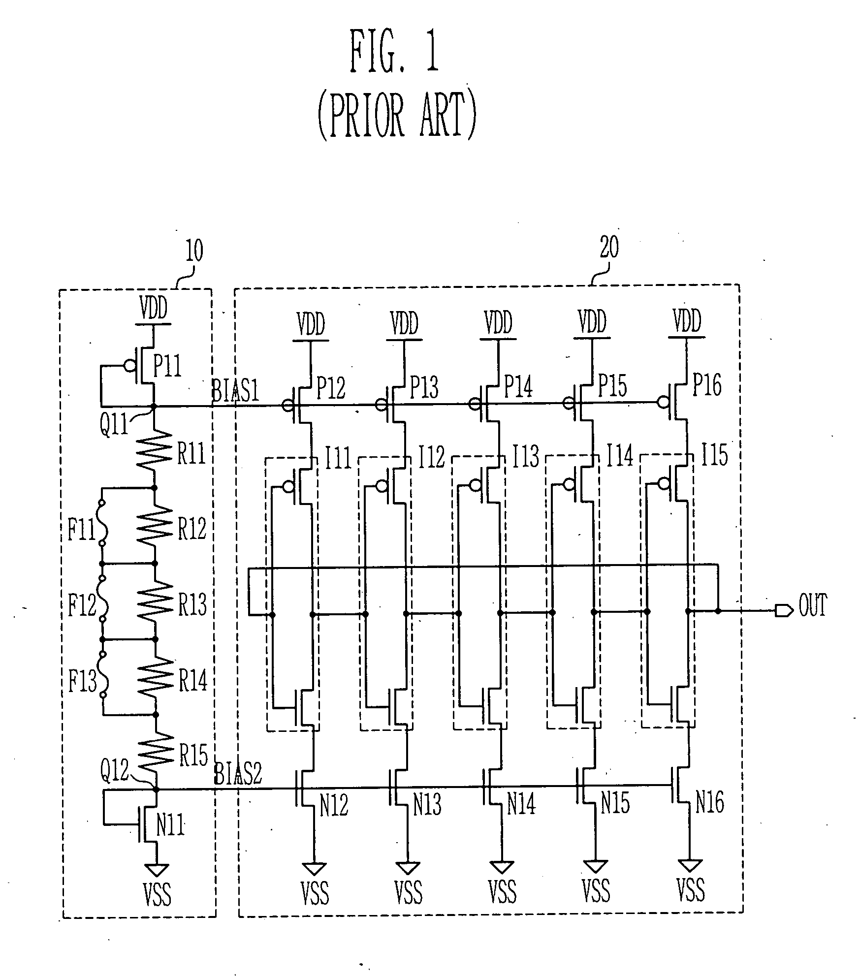
BACKGROUND OF THE INVENTION [0001] 1. Field of the Invention [0002] The present invention relates to a refresh oscillator, and more particularly to a refresh oscillator which can always generate a constant period of signals regardless of variations of a power supply voltage during a self refresh operation for periodically performing a refresh operation in a DRAM. [0003] 2. Description of the Background Art [0004] A self refresh oscillator is used to guarantee a self refresh operation period for repeating a refresh operation in a DRAM after a predetermined time. The self refresh oscillator generates a constant period of signals and determines a self refresh period using the signals. [0005]FIG. 1 is a circuit diagram illustrating a conventional refresh oscillator, including a biasing circuit 10 for determining levels of first and second biases BIAS1 and BIAS2 by controlling resistance of resisters R11 to R15 between diode-coupled PMOS transistor P11 and NMOS transistor N11 by using fu...

Claims


Application Information

Patent Timeline
IPC IPC(8): G11C11/406H03B1/00
CPCG11C11/406
Inventor GOU, JA SEUNG
Owner SK HYNIX INC
Learn More