
Spatio-temporally incremental fiber swept source

a fiber swept source and spatial-temporary technology, applied in the field of optical fiber sources, can solve the problems of blurred images, largely limited image processing speed, and achieve the effect of fast image capture and boost the frame rate of 2d imaging

Active Publication Date: 2018-05-22
THE UNIVERSITY OF HONG KONG
View PDF4 Cites 12 Cited by
  • Summary
  • Abstract
  • Description
  • Claims
  • Application Information

AI Technical Summary

Benefits of technology

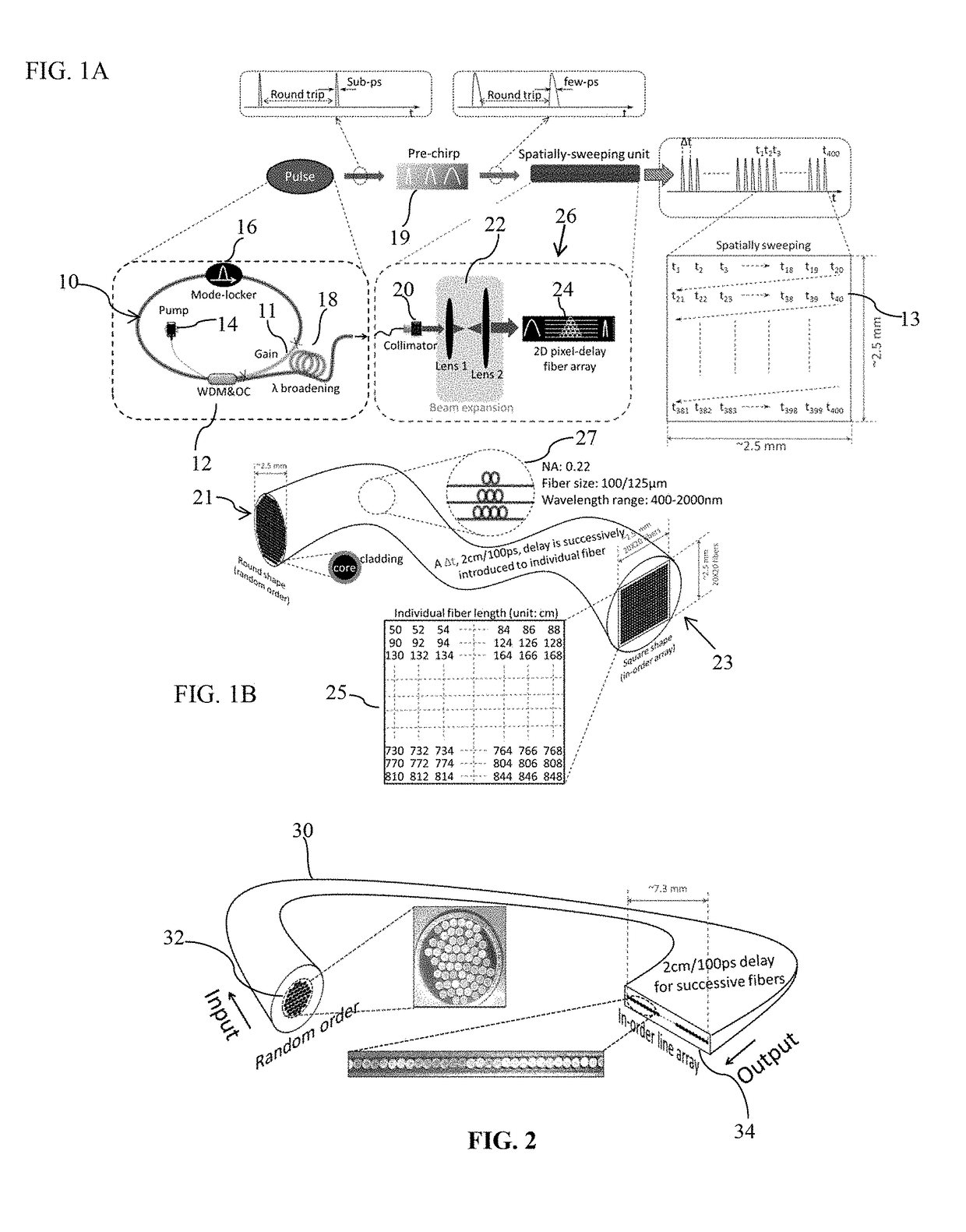
[0007]The present invention provides a 2D spatially-sweeping source, as a new laser source, to overcome all of the limitations mentioned above, and to boost the frame rate of 2D imaging to an unprecedented level—10s of MHz, i.e. 2D image capture within <100 ns. The invention is implemented with a spatio-temporally incremental fiber swept source (STIFSS). With STIFSS a laser beam is applied to one end of a bunch of optical fibers. At the other end of the bunch the fibers are arranged in a raster display. The fibers of the display have different lengths in sequence such that the light beam appears as a raster scan in the display without the need for mechanical or electronic movement of a beam or object. Such fast image capture is crucial for those applications where traditional raster scanning is impossible, particularly for the high-throughput flow cytometers.
[0008]Different from the traditional swept source with a low instantaneous power (mW), the 2D spatially-sweeping STIFSS can provide a peak power up to the kW level, which would allow use in applications such as two-photon or even three-photon confocal microscopy. The dwell time of a single spatial pixel, in addition, is in the order of sub picoseconds (sub-ps)—several orders of magnitude faster than that of CCD / CMOS cameras. Its ultra wide operational wavelength range (more than an octave-spanning), in addition, enables massive applications, e.g. ultrafast multi-photon imaging, spectrally-encoded imaging, hyper-spectral imaging. More importantly, it is a cost-effective solution for optical imaging systems.

Problems solved by technology

Their imaging speed, on the other hand, is largely limited, which results in blurred images.
Typically, there are two main issues that have to be addressed for increasing the effective speed of an optical system: scanning speed and signal readout speed.
Mechanical inertia, unfortunately, limits the moving speed of these bulky stages, typically to several mm / s.
Although in the latter case, i.e., where the beam is moved, can indeed perform the video rate imaging, it is still far from the requirements for a 3D volumetric visualization of those highly dynamic objects.
In addition to the scanning speed, the readout time of the optical signal is another limitation on effectively boosting up the imaging speed, and it must be fast enough to acquire the fast scanning signal.
Traditionally, the optical signal is read out through CCD / CMOS cameras, which however exhibit an unacceptable latency and result in a slow frame rate, typically 100 Hz, and hence a long read-out time.
Unfortunately, the wavelength-swept source is a point source, and it is still necessary to perform point scanning via, e.g., galvanometer scanning, for 2D / 3D imaging.
However, it has the same issue as that of FDML, i.e., extra scanning is required.
The nature of the time-stretch, i.e., high frequency chirping, also limits the instantaneous peak power.
Thus it cannot be used for those applications requiring high peak power, for example multi-photon imaging.

Method used


Image

  • Spatio-temporally incremental fiber swept source
  • Spatio-temporally incremental fiber swept source
  • Spatio-temporally incremental fiber swept source

Examples


Embodiment Construction

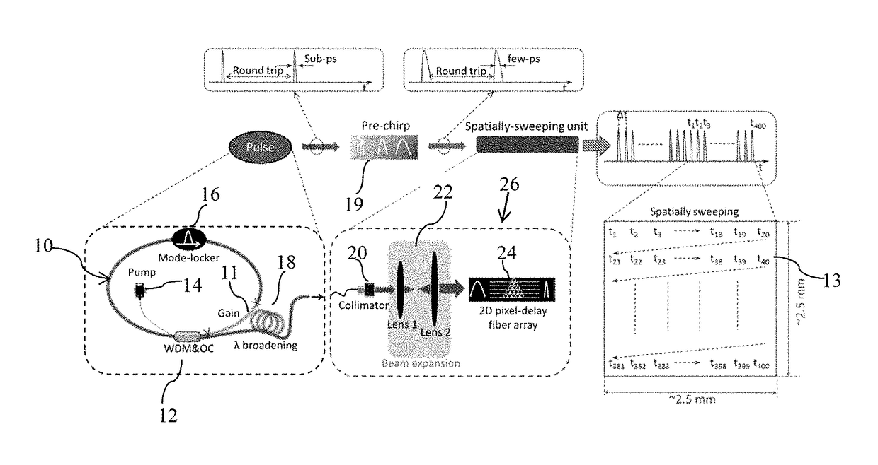
[0021]The spatio-temporally incremental fiber swept source (STIFSS) of the present invention provides an ultrafast inertia-free spatially-scanning laser pulse for each frame of imaging. The sub-ps pulse train is linearly mapped into a 2D spatial distribution by a differential time delay in the fibers of a fiber array as shown in FIG. 1B. Each spatial pixel offers a sub-ps dwell time. This completely-new laser source can be directly applied to existing optical imaging systems and it can perform 2D imaging at a frame rate of 10s MHz, which is several orders of magnitude faster than that of mechanical raster scanning systems, which typically operate in the range of kHz.

[0022]As shown in FIG. 1A the STIFSS can be divided into three parts: 1) high power ultra-short pulse generation (ultrafast femtosecond (fs) pulse generation) with wavelength window management, 2) pulse pre-chirp and 3) ultrafast spatial sweeping. For the high power ultrashort pulse generation, a simple fiber ring cavity...


PUM


Abstract

A spatio-temporally incremental fiber sweep source includes a laser light pulse generator for generating light pulses and a fiber array of individual optical fibers. The fiber array has an input end and an output end, with the fibers at the input end receiving the light pulses substantially simultaneously. The optical fibers at the output end are arranged in a raster scan pattern, e.g., a square pattern, wherein the optical delay in each fiber is greater than the previous one in the scan pattern direction. As a result light exits the array in a completely optical two dimensional raster scan pattern. It has no moving parts, and thus no mechanical inertia, so extremely high speed scanning can be achieved.

Description

FIELD OF THE INVENTION[0001]The present invention relates to an optical fiber source for providing ultrafast inertia-free spatially-scanning laser pulses.BACKGROUND OF THE INVENTION[0002]Optical imaging has drawn great attention from various areas in the past decade, particularly industrial inspection and biomedical diagnosis. As the scientific research has gone deeper and deeper into the details of these areas, people have become more and more interested in dynamic behaviors, especially those involved in life science, e.g. hemokinesis, cytology and neurology, which provide information that may help provide a better understanding of the human body. In particular there is great interest in ultrafast dynamic diagnosis of disease and other tissue functionality. To visualize high-speed dynamic events, an optical imager is required to provide high sensitivity and high throughput. Modern photo-receivers can offer excellent sensitivity, e.g. widely-used CCD / CMOS cameras and photomultiplier...

Claims


Application Information

Patent Timeline
Patent Type & Authority Patents(United States)
IPC IPC(8): G02B6/04H01S3/11G02B6/293G02B6/32H01S3/0941G02B6/42H01S3/094H01S3/067H04N7/18
CPCG02B6/04G02B6/2938G02B6/32G02B6/4285H04N7/18H01S3/0941H01S3/094053H01S3/1106H01S3/06791H04N7/22G02B6/29359H01S3/094007H01S3/09415H01S3/1608H01S3/1616H01S3/1618H01S3/005H01S3/0057H01S3/0092G02B6/0008G02B2006/0098G02B6/4204G02B6/4296
Inventor WONG, KENNETH KIN YIPWEI, XIAOMING
Owner THE UNIVERSITY OF HONG KONG
Learn More