
Light modulating device

a light modulating device and light technology, applied in the direction of optics, holographic process, holographic nature/properties, etc., can solve the problems of high calculation effort, modulation of coherent light, and method that is usually not applicable to holographic us

Inactive Publication Date: 2011-05-26
SEEREAL TECHNOLOGIES
View PDF9 Cites 72 Cited by
  • Summary
  • Abstract
  • Description
  • Claims
  • Application Information

AI Technical Summary

Benefits of technology

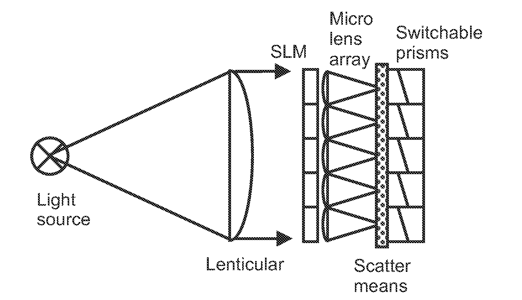
[0058]In a holographic display according to any of the Claims 73 to 78 with the light modulating device of Claim 32, the scatter means can be designed such that a suppression of higher diffraction orders in the plane of a virtual observer window (VOW) of a holographic display is achieved.
[0069]Usually, light sources such as LED's or laser diodes can be switched on / off with a frequency of about 50.000 Hz, i.e. much faster than the possible frame rate of a spatial light modulator, being in the range of about 120 to 360 Hz for example. The light sources can be controlled with respect of the emitted light intensity such that light is only emitted in a short period of time when the corresponding pixel of the macropixel is encoded and comprises its physical desired value. Preferably light sources for different light source wavelengths representing the same basic colours are activated in a time shifted manner. Therefore, the achievable frame rate of the display can be higher than the possible frame rate of a spatial light modulator. If e.g. two light sources are used for each basic colour in combination with two different pixels of the macropixel in combination with two different colour filter means being assigned to these two pixels of the macropixel, the overall frame rate of the display can be doubled on the cost of spatial resolution of the spatial light modulator. If more different light sources and different pixels in combination with respectively assigned different colour filter means are used, the overall frame rate of the display can be further increased. This principle can also be used for 2D TFT-LC monitors.
[0073]A basic colour could be red, green or blue. Alternatively, a basic colour could be yellow, cyan or magenta. In general, the basic colours could be suitably selected to generate almost every colour of the colour space. A correction of at least one generated colour can be performed in its value by selecting an appropriate colour temperature value of the at least one colour to be generated. Four basic colours can be used to increase the colour gamut.
[0079]The spatial light modulator can comprise a micromirror unit, the individual mirrors of the micromirror unit comprise layers with a characteristic suitable to modulate the phase and / or the amplitude of the light interacting with the micromirror unit. Alternatively or additionally, the spatial light modulator can comprise a micromirror unit, the pixelated optical element being implemented into the micromirror unit by lowering the maximum reflectivity of individual mirrors of each macropixel down to different predetermined values and / or to generate a fixed offset of the individual mirrors of each macropixel in their height on the substrate which corresponds to a predetermined phase offset between individual pixels.
[0093]In the holographic display, the light modulating device with a homogenizing element could be adapted to be operated such that undesirable eye crosstalk between the observer windows for both eyes of an observer compared to the use of the same light modulating device without homogenizing elements is reduced.

Problems solved by technology

This method is usually not applicable for holographic use, because modulation of coherent light—needed for a hologram reconstruction—can only be obtained from those hologram data displayed at the same time.
But these require high calculation effort and for this reason and other reasons such calculation methods may not be suitable for fast calculation of variable hologram content to be displayed with an SLM.
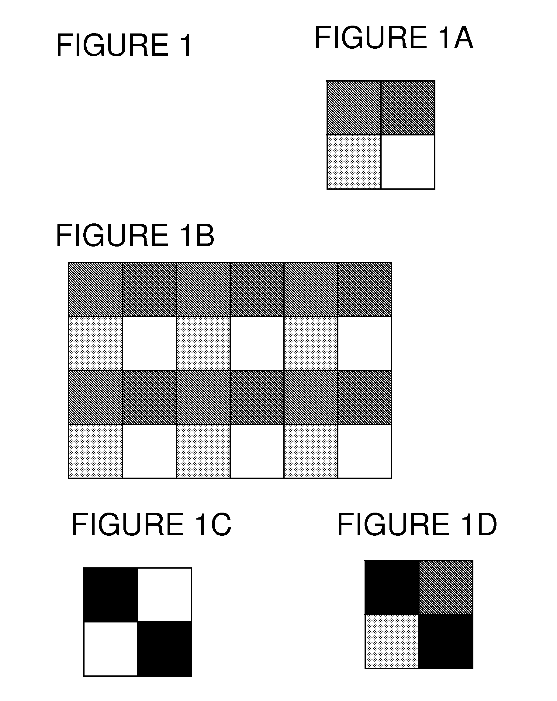
A disadvantage of this method is the fact that with a macropixel composed of N individual binary pixels it is only possible to obtain N+1 grey values.
But this leads to the disadvantage of a higher noise level.

Method used


Image

  • Light modulating device
  • Light modulating device
  • Light modulating device

Examples


Embodiment Construction

[0119]Various implementations will now be described.

[0120]A. Macropixel as a Combination of an SLM and a Fixed Diffractive Element

[0121]The aim is make use of the advantages, for example fast switching times, of SLMs with relatively few quantization steps e.g. binary SLMs, for holographic reconstruction or for other more general light modulation tasks, but to do this in a way such that the disadvantage of these SLMs, i.e. the small number of quantization steps, is compensated for. The meaning of the term ‘relatively few quantization steps’ may depend on the particular setup and may include all cases where the effects of quantization on the result of light modulation may be improved upon to lead to higher quality holographic reconstruction.

[0122]In an example of an implementation, a combined light modulating device, such as a holographic display, is set up in the following manner[0123]a pixelated SLM—with addressable variable content—is combined with a pixelated diffractive element—w...


PUM


Abstract

A light modulating device comprises a spatial light modulator and a homogenizing element. A group of at least two adjacent pixels of the spatial light modulator form a macropixel: The spatial light modulator is of a type such that its pixels comprise a variable content. Each macropixel is used to represent a numerical value which is manifested physically by the states of the pixels of the spatial light modulator which form the macropixel. For each macropixel a homogenizing element is present in the optical path after the macropixel. The homogenizing element comprises an optical input and an optical output. The homogenizing element is adapted such that output light of the macropixel is entering the optical input of the homogenizing element and is mixed within the homogenizing element and is output at the optical output of the homogenizing element.

Description

BACKGROUND OF THE INVENTION[0001]1. Field of the Invention[0002]The invention relates to the field of light modulating devices, especially to light modulating devices used in holographic displays.[0003]2. Technical Background[0004]Computer-generated video holograms (CGHs) are encoded in one or more spatial light modulators (SLMs); the SLMs may include electrically or optically controllable cells. The cells modulate the amplitude and / or phase of light by encoding hologram values corresponding to a video-hologram. The CGH may be calculated e.g. by coherent ray tracing, by simulating the interference between light reflected by the scene and a reference wave, or by Fourier or Fresnel transforms; CGH calculation methods are described for example in US2006 / 055994 and in US2006 / 139710, which are incorporated by reference. An ideal SLM would be capable of representing arbitrary complex-valued numbers, i.e. of separately controlling the amplitude and the phase of an incoming light wave. Howe...

Claims


Application Information

Patent Timeline
IPC IPC(8): G03H1/08G02B26/00
CPCG02F1/133524G03H1/02G03H1/22G03H2240/42G03H2001/0224G03H2225/33G03H2225/55G03H1/2294G03H2223/53G03H2250/34
Inventor FUTTERER, GERALDKROLL, BOBUSCHBECK, STEFFEN
Owner SEEREAL TECHNOLOGIES
Learn More