System having a process chamber for workpieces

a technology of process chamber and workpiece, which is applied in the direction of vehicle body drying, drying machines, light and heating apparatus, etc., can solve the problems of impure impurities, dust particles, etc., and achieve the effect of efficient thermal separation of the inner space, adequate fresh air supply, and simple means

Active Publication Date: 2018-05-15
DUERR SYST AG
View PDF42 Cites 16 Cited by
  • Summary
  • Abstract
  • Description
  • Claims
  • Application Information

AI Technical Summary

Benefits of technology

[0005]An object of the invention is to provide an installation having a process chamber which has an inner space which has a receiving region for workpieces and which can be opened at least partially, in which installation an efficient thermal separation of that inner space from the environment is possible with simple means and, at the same time, an adequate fresh air supply for the receiving region can be ensured.

Problems solved by technology

The coat of paint or coating of the vehicle bodyworks to be dried may be impaired by impurities, in particular particles of dust.

Method used


Image

  • System having a process chamber for workpieces
  • System having a process chamber for workpieces
  • System having a process chamber for workpieces

Examples


Embodiment Construction

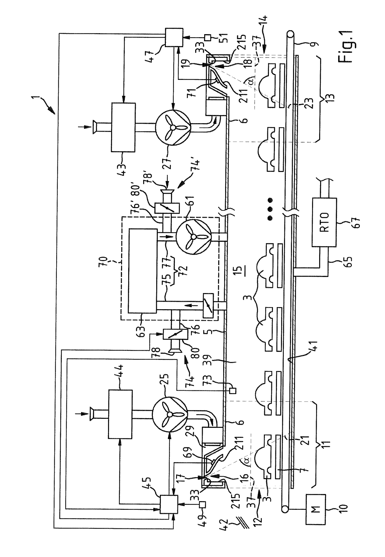
[0050]The installation 1 shown in FIG. 1 for drying, for example, metal workpieces is configured in particular for vehicle bodyworks 3. The installation 1 comprises a process chamber which is in the form of a drying tunnel 5. The vehicle bodyworks 3 which are mounted on skids 7 can be moved through the drying tunnel 5 by means of a conveying device 9. The conveying device has an electrical drive 10. The drying tunnel 5 is lined with sheet metal. It has an inlet lock 11 having an inlet opening 12 and an outlet lock 13 having an outlet opening 14. The drying tunnel 5 comprises a drying zone 15 which is located between the inlet lock 11 and the outlet lock 13. The drying zone 15 is a receiving region for workpieces. The drying zone 15 is preferably configured in such a manner that approximately fifteen vehicle bodyworks 3 which are freshly coated with a substrate which contains paint and / or a solvent can be dried therein more or less at the same time. To this end, the drying portion 15...


PUM


Abstract

The invention relates to an installation having a process chamber which comprises an inner space having a receiving region for workpieces. The process chamber has an opening for the supply or discharge of workpieces. The process chamber is constructed so as to have a device for the introduction of gaseous fluid into the inner space, which device has at least one nozzle or aperture for the production of a fluid stream curtain between the opening and the receiving region for workpieces. The process chamber has a device for supplying fresh air, with which device fresh air can be introduced into the receiving region at a side of the fluid stream curtain, which side faces away from the opening.

Description

CROSS REFERENCE TO RELATED APPLICATIONS[0001]This application is a continuation-in-part application of patent application Ser. No. 14 / 398,721, filed Nov. 3, 2014, which, in turn, is the national stage of PCT / EP2013 / 058817, filed Apr. 26, 2013, designating the United States and claiming priority from German patent application no. 10 2012 207 312.4, filed May 2, 2012, the entire contents of which are incorporated herein by reference.FIELD OF THE INVENTION[0002]The invention relates to an installation having a process chamber which has an inner space having a receiving region for workpieces and which has an opening for the supply or discharge of workpieces and which has a device for the introduction of gaseous fluid into the inner space, which device comprises at least one nozzle or aperture for the production of a fluid stream curtain between the opening and the receiving region for workpieces.BACKGROUND OF THE INVENTION[0003]Such an installation is known from WO 2010 / 122121 A1.[0004]...

Claims


Application Information

Patent Timeline
Patent Type & Authority Patents(United States)
IPC IPC(8): F26B25/00F26B21/00F26B21/12F26B21/10F26B23/02
CPCF26B25/008F26B21/004F26B21/12F26B23/022F26B21/10F26B2210/12
Inventor WIELAND, DIETMARIGLAUER, OLIVERKNUESEL, CHRISTOFWINKLER, MARIUS
Owner DUERR SYST AG
Why Eureka
Try Eureka