Energy allocation system for balancing energy consumption

a technology of energy allocation and energy consumption, applied in adaptive control, process and machine control, instruments, etc., can solve the problems of limiting the availability of natural energy resources, fossil fuels in particular, affecting the environment, and unable to be replaced and/or detrimentally impacted by the environment,

Inactive Publication Date: 2018-04-17
INT BUSINESS MASCH CORP
View PDF23 Cites 1 Cited by
  • Summary
  • Abstract
  • Description
  • Claims
  • Application Information

AI Technical Summary

Benefits of technology

[0011]Preferably, in the step of supplying energy to the device, the power provided to the device at any given point in time is selected to be within a range defined by, and between, the limits specified by the upper power function and the lower power function. By determining a power flexibility range as given by the upper power function and the lower power function and energy demand prediction as given by the upper energy function and the lower energy function, a supplier of power / energy resource has flexibility in terms of time and power supplied to a given energy storage device, which extends the advantage of versatility to an embodiment of the present invention.
[0013]According to an embodiment of a second aspect of the present invention, there is provided an energy allocation system for allocating energy to at least a given set of energy storage devices that are arranged in a hierarchical tree of nodes comprising at least a parent node with corresponding children nodes, thereby to substantially balance energy consumption by each of the energy storage devices with the energy supplied thereto, the system comprising: at least a prediction layer being configurable to predict at least a demand for energy in discrete time-slots in a given planning time-period in the future and to generate power flexibility data for each of the energy storage devices in the given set from information on an energy status and event status of each of the devices at a given point in time; an aggregation layer comprising an aggregation sub-layer that is configurable to hierarchically aggregate the energy demand prediction and power flexibility data for the given set of energy storage devices, and an aggregation top-layer that is configurable to aggregate the results of the aggregation sub-layer, thereby to obtain data on the total energy demand prediction and power flexibility for the given set of energy storage devices; an allocation layer, which is configurable to generate a reference power supply curve indicating the power available for supply in the discrete time-slots of the planning time-period to the given set of energy storage devices based on the aggregation results received from the aggregation top-layer and a prediction on the energy supply by a given energy resource that has been selected to supply energy to the given set of energy storage devices, wherein the aggregation layer is configurable to hierarchically disaggregate the reference power supply curve into individual power supply curves for provision to each of the energy storage devices in the given set of energy storage devices, thereby giving each of the energy storage devices a corresponding power schedule to be followed on when to consume energy and how much energy to consume in a given point in time when the energy storage device is in use in the given planning time-period. In this way, energy consumption of a relatively large number of energy storage devices may be tailored to follow the energy generation, which is of particular benefit when the energy resource selected for supplying energy is a fluctuating energy resource such as a renewable energy resource. Furthermore, scaling is an advantage due to the hierarchical arrangement in an embodiment of the present invention. A still further advantage is that boundaries on the power flexibility and the energy demand are provided at the aggregation level / layer, thus, the allocation layer being the top-level in the hierarchy has a knowledge of the aggregated boundaries associated with the energy storage devices at the bottom of the hierarchy.

Problems solved by technology

It is globally acknowledged that the depletion of natural energy resources, environmental issues arising from the use thereof and the lack of alternative energy resources are but some of the issues that impact the profile of the energy landscape of the future.
However, such natural energy resources, and fossil fuels in particular, are becoming scarce, cannot be replaced and / or detrimentally impact the environment.
However, there are short-term risks such as incidences associated with nuclear fission as well as long term issues such as storage and / or disposal of radioactive waste resulting from nuclear fission.
However, there are some issues associated with renewable energy resources, which restrict them from providing a suitable alternative to and / or completely replacing fossil fuels for the generation of energy.
One such issue is that renewable energy resources are time-variant in their occurrence—the wind does not always blow and the solar irradiance depends on the time of the day and on cloud movement.
A further issue is that renewable energy resources may be area-specific in that they may occur more abundantly in some areas compared to others, such as, for example, coastal regions and deserts, which may be far away from the demand of such resources, thereby necessitating the consideration of transport issues to the location(s) of the demand.
However, for certain energy forms, such as, for example, electrical energy, it may be a challenge to provide energy storage devices with sufficient capacity, if at all.
Other methods such as, for example, hydrogene extraction and compressed air have associated technical limitations and so are not widely used.
As for electrical accumulator technology, it is costly and may be considered to have inadequate storage density, thus space and other resources may have to be facilitated for its implementation in a realistic energy chain scenario.
Whilst energy constraints have been expressed in terms of the maximum and minimum total energy that can be stored in a device, these terms are static and do not reflect the time-varying need of stored energy as related to energy consumption and inflowing power / energy.

Method used


Image

  • Energy allocation system for balancing energy consumption
  • Energy allocation system for balancing energy consumption
  • Energy allocation system for balancing energy consumption

Examples


Embodiment Construction

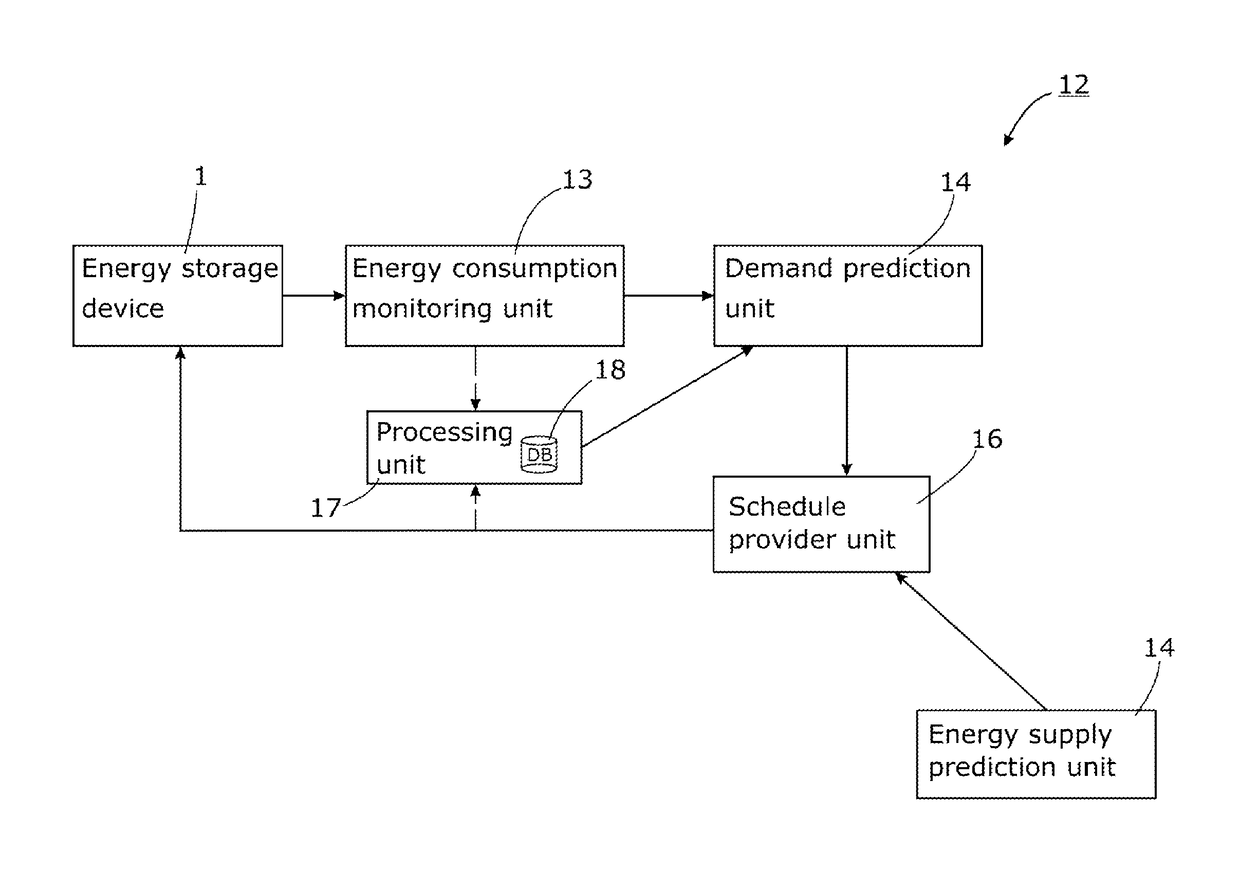
[0023]It is desirable to be able to address the energy goals of demand units, that is, providing power to the demand unit over a given time-period thereby to facilitate a desired operation, and to do so while taking advantage of the inherent, albeit limited, flexibility of energy storage devices. Particularly, it is a challenge to facilitate that the energy consumption by a relatively large number of energy storage devices follows the supply / generation of energy by an energy provider. Within the description, the same reference numbers or signs are used to denote the same parts or the like.

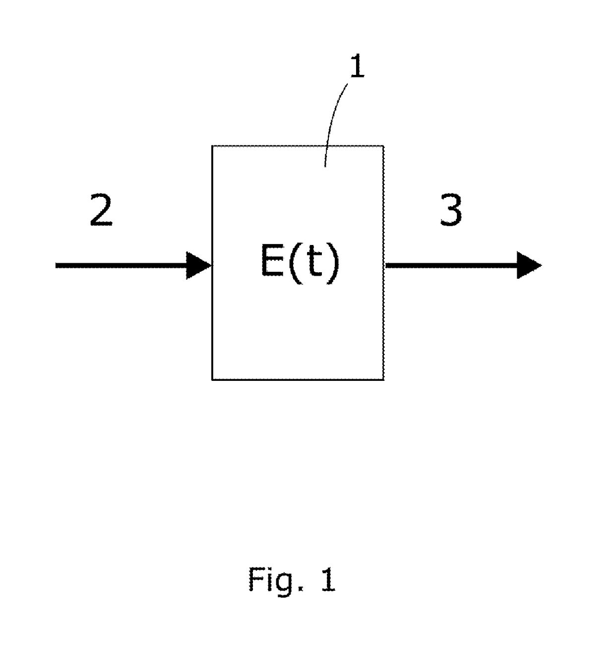
[0024]Reference is now made to FIG. 1, which schematically illustrates the principle of a device model in an embodiment of the present invention. The device is preferably an energy storage / buffering device 1 and may, for example, be the battery of an electric vehicle or a hot-water boiler. Generally, in an embodiment of the present invention, the energy storage device 1 may be a device capable of f...


PUM


Abstract

The present invention relates to an energy allocation system for operating at least an energy storage device to substantially balance the energy consumed by the energy storage device with the energy supplied thereto, comprising the steps of: determining a power flexibility of the energy storage device by generating an upper time-varying power function; predicting energy consumption data per discrete time-slots over a given time-window for the device; predicting a demand for energy by the device in a given planning time-period; generating a time-varying upper energy function for the demand prediction that defines an uppermost limit for the supply of energy to the device; generating a time-varying lower energy function for the demand prediction that defines a lowermost limit for the supply of energy to the device, and supplying energy to the device in a range defined by the limits specified by the upper energy function and the lower energy function.

Description

CROSS-REFERENCE TO RELATED APPLICATIONS[0001]This is a U.S. National Phase application which claims priority to International Application PCT / IB2012 / 057472, filed Dec. 19, 2012, which in turn claims priority to Patent Application No. EP 11195646.2, filed on Dec. 23, 2011. The contents of both of these applications are incorporated herein by reference in their entireties.FIELD OF THE INVENTION[0002]The present invention relates to an energy allocation system for allocating energy to a given set of energy storage devices thereby to substantially balance energy consumption by each of the energy storage devices with the energy supplied thereto. The present invention also extends to a control loop for allocating energy to, and a method of operating, an energy storage device thereby to substantially balance energy consumption by the energy storage device with the energy supplied thereto.BACKGROUND OF THE INVENTION[0003]It is globally acknowledged that the depletion of natural energy resou...

Claims


Application Information

Patent Timeline
Patent Type & Authority Patents(United States)
IPC IPC(8): G05D3/12G05B13/02H02J3/28G05F1/66G06Q50/06H02J3/00
CPCG05F1/66G05B13/026G06Q50/06H02J3/28H02J2003/003Y04S40/22Y02E40/76Y02E60/76Y04S10/54Y04S10/545H02J2003/007H02J3/003H02J2203/20Y02E40/70Y02E60/00Y04S10/50Y04S40/20
Inventor BINDING, CARLSUNDSTROEM, OLLE L.
Owner INT BUSINESS MASCH CORP
Why Eureka
Try Eureka