
Brush roll arrangement for a floor cleaning tool

a technology for cleaning tools and brushes, which is applied in the direction of carpet cleaners, cleaning machines, carpet sweepers, etc., can solve the problems of difficult simultaneous achievement of the required secure fixing of the removable bearing, the user of the tool's difficulty in easily removing the removable bearing, and prior art arrangements that have not been able to simultaneously satisfy these opposite demands, etc., to achieve convenient re-installation, easy removal by hand, and simple structure

Active Publication Date: 2006-03-30
STEIN
View PDF8 Cites 143 Cited by
  • Summary
  • Abstract
  • Description
  • Claims
  • Application Information

AI Technical Summary

Benefits of technology

[0004] In view of the above, it is an object of the invention to provide a brush roll arrangement that includes a particularly simple construction of a removable bearing that can be easily removed by hand, and can again easily be re-installed by hand to achieve a securely fixed installed condition. A further object of the invention is to provide a removable bearing arrangement in which a rotating motion allows the bearing to be released or secured as desired, and the released bearing can be axially removed from an end of the brush roll arrangement, to allow the removal of the brush roll. The invention further aims to avoid or overcome the disadvantages of the prior art, and to achieve additional advantages, as apparent from the present specification. The attainment of these objects is, however, not a required limitation of the claimed invention.

Problems solved by technology

However, it has been found in practice, that it is difficult for the user of the tool to easily remove the removable bearing without the need of tools, and particularly through simple manipulations by hand.
It has further been difficult to simultaneously achieve the required secure fixing of the removable bearing in its installed condition to ensure a sufficient operating safety.
In other words, the prior art arrangements have been unable to simultaneously satisfy these opposite demands, namely easy removability of the bearing by hand, and also secure fixing of the bearing in its installed condition.

Method used


Image

  • Brush roll arrangement for a floor cleaning tool
  • Brush roll arrangement for a floor cleaning tool
  • Brush roll arrangement for a floor cleaning tool

Examples


Embodiment Construction

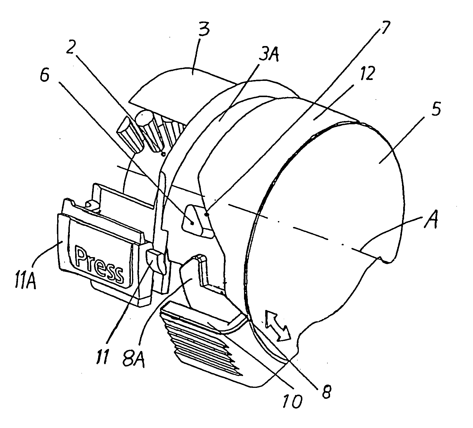
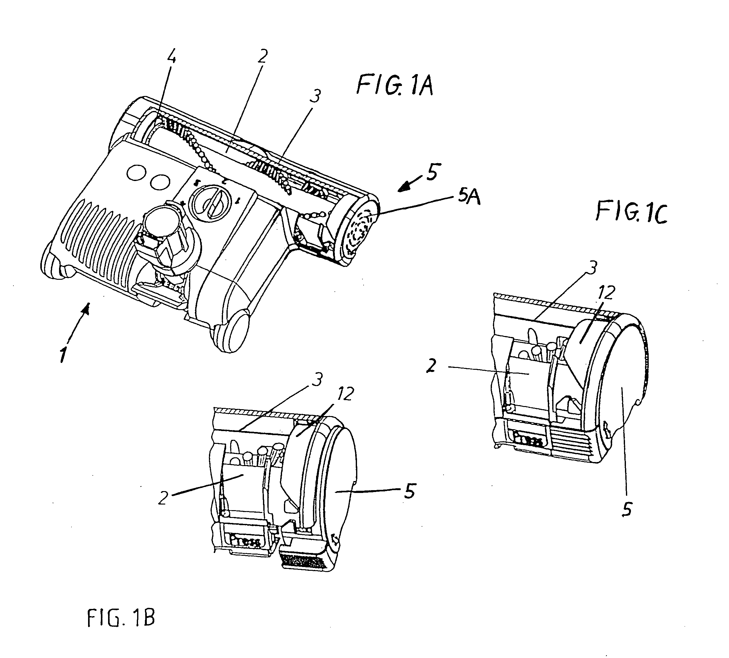
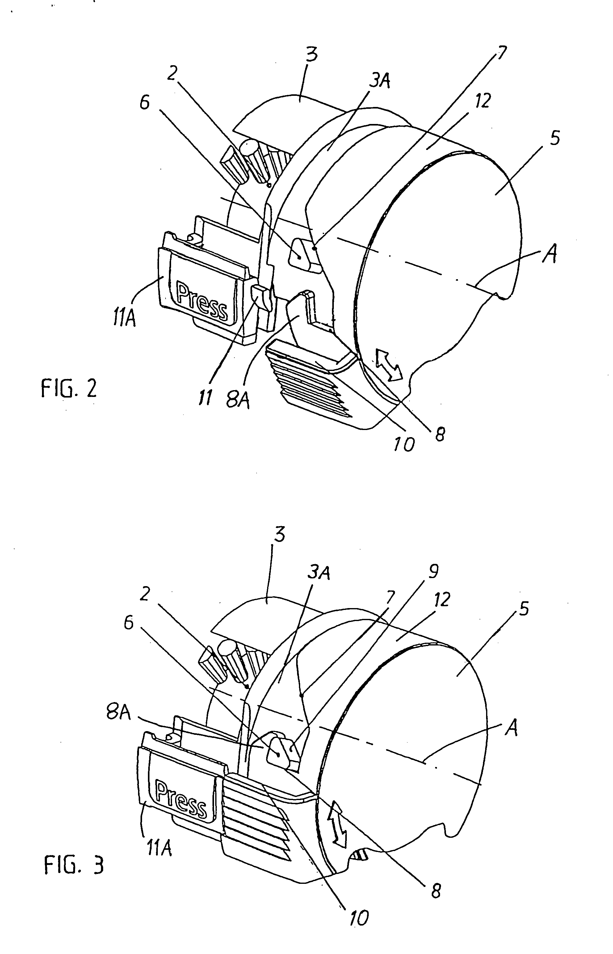
[0016] In the illustrated example, the vacuum cleaner brush head, floor cleaning tool, or brush tool 1 includes a rotatable brush roll 2 arranged in a brush housing 3. The brush roll 2 is rotatably supported at two opposite ends thereof by respective rotation bearings 4 and 5A. While the bearing 4 may be a conventional fixed bearing that is fixedly secured in the brush housing 2, the bearing 5A is incorporated in a removable bearing arrangement 5 according to the invention. This removable bearing arrangement 5 is selectively secured to the brush housing 3 to rotatably support the brush roll 2, or is selectively removable to allow the brush roll 2 to be removed from the housing 3 (for example for cleaning, maintenance, or replacement of the brush roll 2). The removable bearing arrangement 5 and the brush roll 2 can be removed from the housing 3 in the axial direction, i.e. parallel to the axis A of the brush roll 2 and the housing 3.

[0017] The removable bearing arrangement 5 include...


PUM


Abstract

A brush roll is rotatably supported by bearings in a housing of a cleaning brush tool. One of the bearings is incorporated in a removable bearing arrangement that can be rotationally fastened and removed as needed on a cylindrical end of the housing. Preferably collar elements protruding cylindrically from the removable bearing arrangement form bayonet-type catch hooks that selectively engage with bayonet-type catch elements protruding radially outwardly from the cylindrical end sleeve of the housing. A detent on the housing engages a securing element on the removable bearing arrangement to secure the engaged bayonet-type fastening arrangement against rotational release thereof.

Description

PRIORITY CLAIM [0001] This application is based on and claims the priority under 35 U.S.C. §119 of German Patent Application 10 2004 046 383.2, filed on Sep. 24, 2004, the entire disclosure of which is incorporated herein by reference. FIELD OF THE INVENTION [0002] The invention relates to a brush roll arrangement for a cleaning tool, such as a floor cleaning tool, a carpet cleaning tool, an upholstery brush tool or a brush tool head of a vacuum cleaner, having at least one rotating brush roll supported by bearings. BACKGROUND INFORMATION [0003] Brush roll arrangements of the above mentioned general type are known in various different configurations and embodiments, particularly in relation to brush tools for vacuum cleaners. In such a brush roll arrangement, it is conventionally known that at least one of the bearings supporting the brush roll may be a removable bearing, i.e. so that this bearing can be removed to allow removal of the brush for cleaning and maintenance purposes. Va...

Claims


Application Information

Patent Timeline
Patent Type & Authority Applications(United States)
IPC IPC(8): A47L11/24
CPCA47L9/0455
Inventor STEIN, THOMASLIFFERS, ACHIM
Owner STEIN
Learn More