
Micropatterned intraocular implant

a micro-patterned, intraocular technology, applied in the field of intraocular implants, can solve the problems of inconvenient systemic administration of drugs for localized ocular conditions, cumbersome and confusing drop schedule, and difficulty in topical drops for young and elderly

Inactive Publication Date: 2018-04-17
SHARKLET TECH +2
View PDF104 Cites 0 Cited by
  • Summary
  • Abstract
  • Description
  • Claims
  • Application Information

AI Technical Summary

Benefits of technology

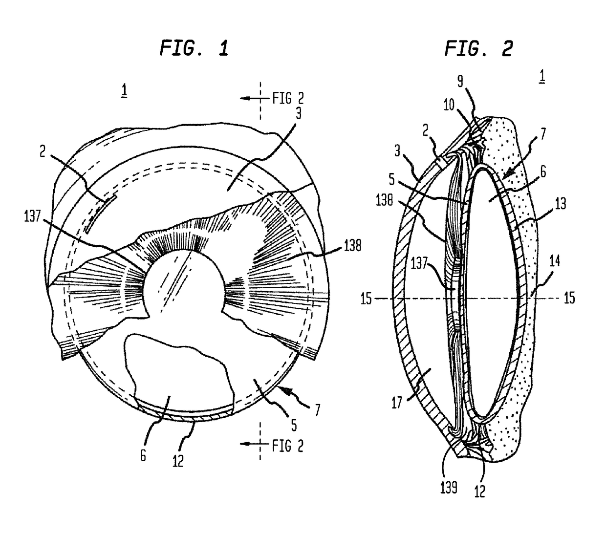
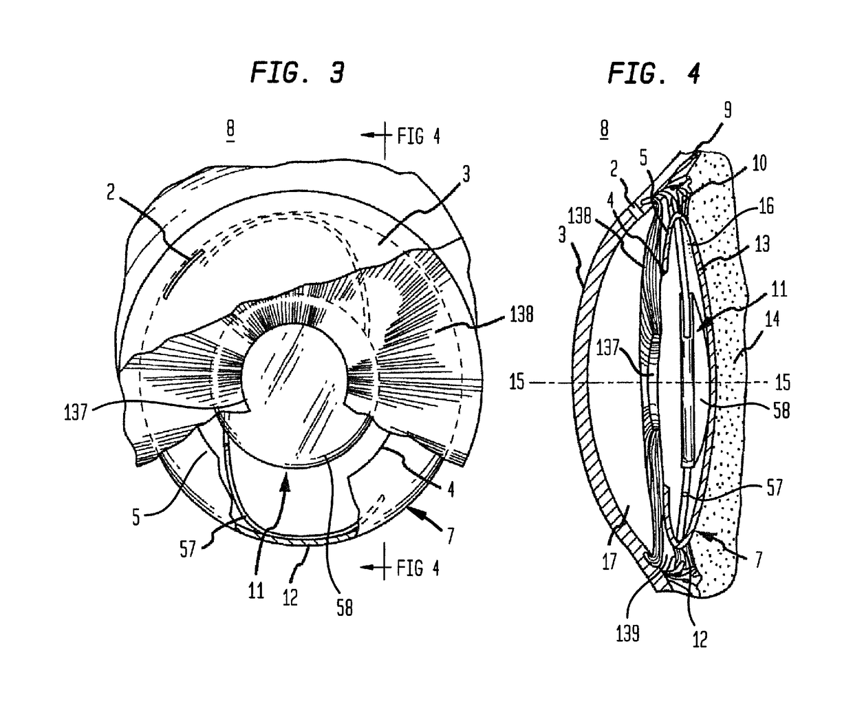
The invention provides a biocompatible intraocular implant that can be used during cataract surgery to prevent the migration or growth of residual lens epithelial cells (LECs) on the posterior capsule of the eye. This helps to reduce the risk of posterior capsule opacification (PCO) and other complications associated with cataract surgery. The implant can be made from non-biodegradable or biodegradable materials and can be located between the surface of the posterior capsule and the implanted intraocular lens (IOL) to provide a mechanical barrier and inhibit the growth or migration of residual LECs.

Problems solved by technology

Another prominent problem with routine cataract surgery and other surgical procedures such as retinal surgery, cornea transplant surgery, glaucoma surgery, or the like, can be postoperative administration of antibiotics to prevent endophthalmitis.
However, there has yet to be a prospective randomized study showing that topical antibiotics prevent endophthalmitis.
Topical drops can be difficult for young and elderly patients and the drop schedule can be cumbersome and confusing particularly when following surgery each eye (1)(8) is on a different drop schedule.
These difficulties can result in non-compliance with serious consequences such as endophthalmitis, glaucoma, and cystoid macular edema.
Also, the systemic administration of drugs for treatment of localized ocular conditions may not be preferred because of the inefficiency associated with indirect delivery of the drugs to a target organ.
However, patients can be intolerant of these devices due to difficulty in insertion and removal and mild to moderate conjunctival irritation during use which may explain why external ocular inserts have not been widely accepted in clinical practice.

Method used


Image

  • Micropatterned intraocular implant
  • Micropatterned intraocular implant
  • Micropatterned intraocular implant

Examples


example 1

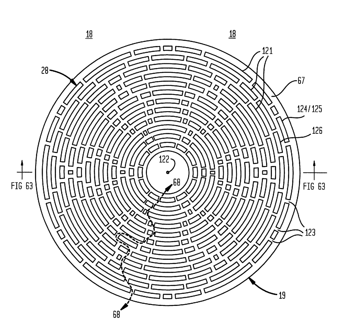
[0213]Now referring primarily to FIGS. 39 through 42 smooth and patterned flexible membranes (19) were fabricated by casting biomedical grade polydimethylsiloxane elastomer (“PDMSe”, SILASTIC® MDX4-4210; Dow Corning, Midland, Mich.) against negative silicon wafer molds. The flexible membranes (19) produced by this method included a plurality of patterned surface elements (28) and non-linear channel elements (71) arranged in a pattern (72) as shown in the examples of FIGS. 39 through 42 that either protruded from the surface of the PDMSe flexible membrane (19) as shown in the example of FIGS. 39 and 40 or were recessed into the PDMSe flexible membrane (19) as shown in the examples of FIGS. 41 and 42. A pattern (72) with patterned surface elements (28) protruding 3 μm from the surface of the flexible membrane (19) that were 2 μM wide and spaced by 2 μm would be called +3SK2×2. The patterns (72) replicated for testing included smooth unpatterned “SM”, −3SK2×2, +3SK2×2, and +7SK10×5.

example 2

[0214]Now referring primarily to FIGS. 79A through 79C and 80, circular flexible membranes (19)(diameter=about 20 mm) including “SM”, “+1SK10×5”, and +10SK50×50 samples were adhered to a 12-well plate with the axis A′-A′ (101) of the plurality of groups of surface elements (78) of the “+1SK10×5”, and “+10SK50×50” samples aligned orthogonal to the direction of cell adhesion, growth or migration (107) and treated with 15 μg / mL fibronectin (BD Biosciences, San Jose, Calif.) in phosphate buffered saline (Life Technologies, Carlsbad, Calif.) overnight to facilitate cell attachment. A modified scratch-wound assay was created by blocking cell attachment to the samples using SM PDMSe rectangles (3 mm×320 mm) placed along the center of the flexible member (19) to simulate wound areas (140). LECs (16)(ATCC CRL-11421; ATCC, Manassas, Va.) were seeded over the entire assembly at about 1×10⁴ cells / cm2 and maintained in growth media (Eagle's Minimum essential media; ATCC), 20% fetal bovine serum ...

example 3

[0215]Now referring primarily to FIGS. 81A through 81D and 82, circular flexible membranes (19)(diameter=about 20 mm) including “SM”, −3SK2×2, +3SK2×2, and +7SK10×5 samples were adhered to a 12-well plate with the axis A′-A′ (101) of the plurality of groups of surface elements (78) of the −3SK2×2, +3SK2×2, and +7SK10×5 samples aligned orthogonal to the direction of cell adhesion, growth or migration (107) and treated with 15 μg / mL fibronectin (BD Biosciences, San Jose, Calif.) in phosphate buffered saline (Life Technologies, Carlsbad, Calif.) overnight to facilitate cell attachment. A modified scratch-wound assay was created by blocking cell attachment to the samples using SM PDMSe rectangles (3 mm×320 mm) placed along the center of the flexible member (19) to simulate wound areas (140). LECs (16)(ATCC CRL-11421; ATCC, Manassas, Va.) were seeded over the entire assembly at 1×10⁴ cells / cm2 and maintained in growth media (Eagle's Minimum essential media; ATCC), 20% fetal bovine serum ...


PUM


Abstract

Generally, an intraocular implant having on the external surface a plurality of pattern surface elements disposed in spaced apart relation defining a tortuous pathway adapted to control a flow of fluid, or a flow of particles suspended in a fluid, or inhibits the growth or migration of cells. In particular, an intraocular implant which implanted between an intraocular lens and the surface of the posterior capsule of the eye inhibits growth or migration of residual lens epithelial cells after cataract surgery by providing structural barriers to reduce posterior capsule opacification of the eye.

Description

[0001]This United States Patent Application is a continuation-in-part of U.S. patent application Ser. No. 14 / 298,318, filed Jun. 6, 2014, which is a continuation of U.S. patent application Ser. No. 13 / 944,817, filed Jul. 17, 2013, now U.S. Pat. No. 9,204,961 which is a continuation of U.S. patent application Ser. No. 13 / 479,178, filed May 23, 2012, which is a continuation-in-part of U.S. patent application Ser. No. 13 / 136,515, filed Aug. 2, 2011, now abandoned now U.S. Pat. No. 8,551,167, issued Oct. 8, 2013, which is a continuation-in-part of U.S. patent application Ser. No. 12 / 998,652, filed May 13, 2011, which is a United States National Stage of International Patent Cooperation Treaty Patent Application No. PCT / US2009 / 006195, filed Nov. 19, 2009, which claims the benefit of United States Provisional Patent Application 61 / 270,567, filed Jul. 10, 2009 and U.S. Provisional Patent Application No. 61 / 199,674, filed Nov. 20, 2008, and claims the benefit of U.S. Provisional Patent Appl...

Claims


Application Information

Patent Timeline
Patent Type & Authority Patents(United States)
IPC IPC(8): A61F2/16A61F2/14A61F2/00
CPCA61F2/16A61F2/14A61F2/161A61F2/1601A61L2430/16A61F2002/009
Inventor CUEVAS, KEVIN H.REDDY, SHRAVANTHI T.MAGIN, CHELSEA MARIEMETTETAL, MICHAEL R.BRENNAN, ANTHONY B.MAY, RHEA MARIEMANN, ETHAN EUGENE
Owner SHARKLET TECH
Learn More