Comparator and semiconductor device including comparator
a semiconductor device and comparator technology, applied in the field of comparators, can solve the problems of low flexibility of driving method, and inability of chopper comparator to operate as a comparator, so as to achieve high on-state current, reduce initialization frequency, and flexibility of driving method
- Summary
- Abstract
- Description
- Claims
- Application Information
AI Technical Summary
Benefits of technology
Problems solved by technology
Method used
Image

Examples
embodiment 1
[0050]One embodiment of a chopper comparator in the present invention is described.
(Structure of Comparator)
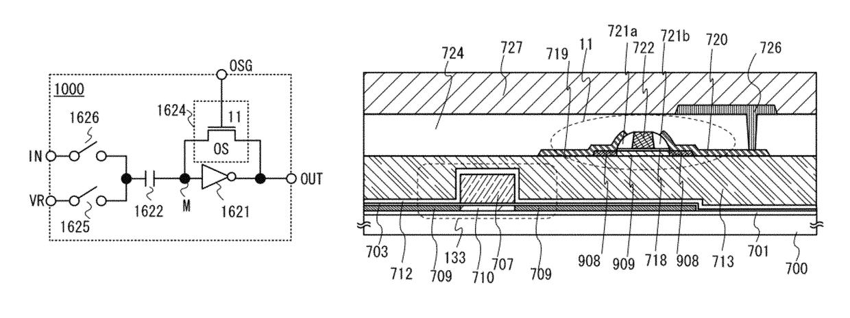
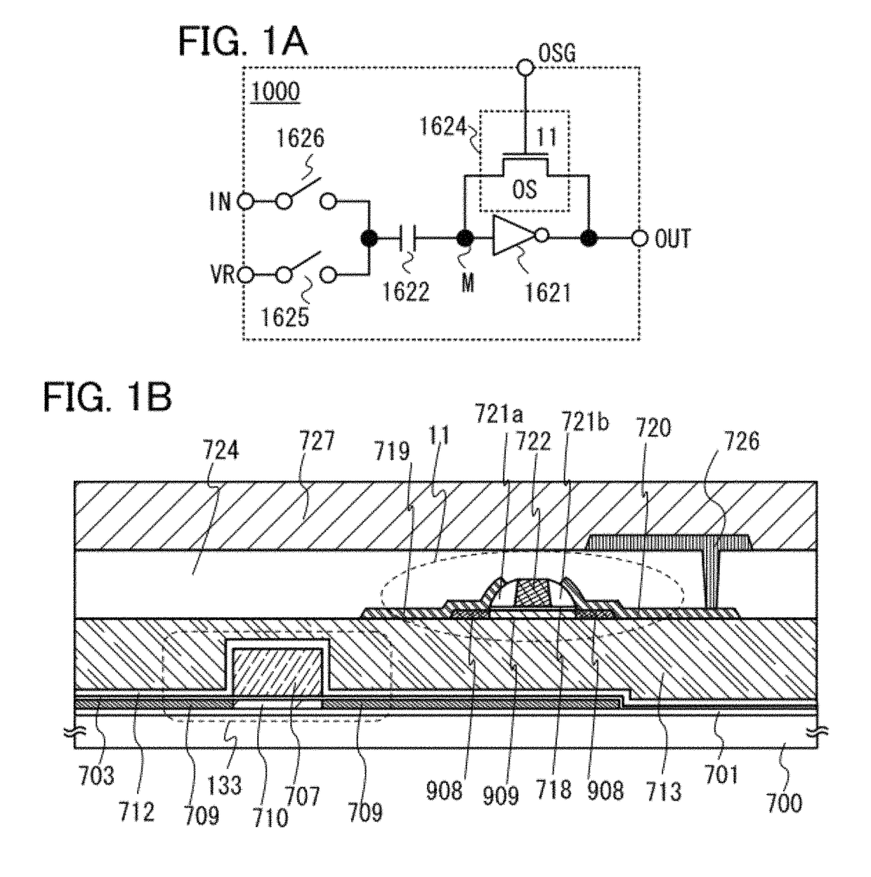
[0051]FIG. 1A is one embodiment of a circuit diagram of a chopper comparator in the present invention. In FIG. 1A, a chopper comparator 1000 includes a switch 1624, a switch 1625, a switch 1626, an inverter 1621, and a capacitor 1622. The switch 1624 is electrically connected in parallel to the inverter 1621. An output terminal of the inverter 1621 is electrically connected to an output terminal (indicated by “OUT” in FIG. 1A) of the chopper comparator 1000. An input terminal of the inverter 1621 is electrically connected to one of a pair of electrodes of the capacitor 1622. Here, the input terminal of the inverter 1621 or the one of the pair of electrodes of the capacitor 1622 is referred to as a node M (indicated by “M” in FIG. 1A). The other of the pair of electrodes of the capacitor 1622 is electrically connected to an input terminal (indicated by “IN” in FIG. 1A) of the c...
embodiment 2
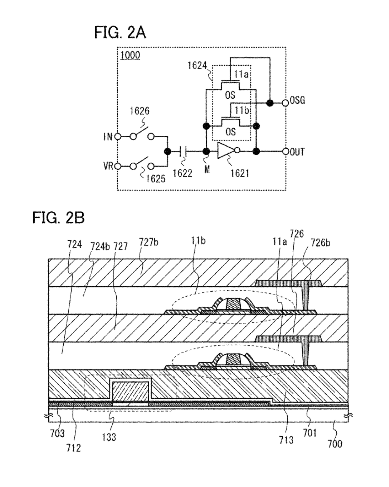
[0062]Another embodiment of a chopper comparator in the present invention is described. FIG. 2A is one embodiment of a circuit diagram of a chopper comparator in the present invention.
[0063]The chopper comparator 1000 in FIG. 2A differs from the chopper comparator 1000 in FIG. 1A in that transistors 11a and 11b electrically connected in parallel to each other are used as the switch 1624, and other structures are similar to those in FIG. 1A; thus, a description thereof is omitted. Note that the switch 1624 is not limited to being constituted of two transistors. A plurality of transistors electrically connected in parallel to each other can be used as the switch 1624. Thus, the value of current flowing through the switch 1624 can be increased, so that initialization can be efficiently performed. Further, heat generation in the transistors can be inhibited.
[0064]A method for driving the comparator 1000 in FIG. 2A is similar to the method for driving the comparator 1000 in FIG. 1A; thus...
embodiment 3
[0068]Another embodiment of a chopper comparator in the present invention is described. FIG. 3A is one embodiment of a circuit diagram of a chopper comparator in the present invention.
[0069]The chopper comparator 1000 in FIG. 3A differs from the chopper comparator 1000 in FIG. 1A in that the transistor 11a and a transistor 11c electrically connected in series with each other, the transistor 11b and a transistor 11d electrically connected in series with each other, and a circuit constituted of the transistors 11a and 11c and a circuit constituted of the transistors 11b and 11d which are electrically connected in parallel to each other are used as the switch 1624. Other structures are similar to those in FIG. 1A; thus, a description thereof is omitted. Note that the switch 1624 is not limited to being constituted of four transistors. A plurality of transistors electrically connected in series and in parallel to each other can be used as the switch 1624. This structure can also be refe...
PUM
 Abstract
Description
Claims
Application Information
 - R&D
- Intellectual Property
- Life Sciences
- Materials
- Tech Scout
- Unparalleled Data Quality
- Higher Quality Content
- 60% Fewer Hallucinations
Browse by: Latest US Patents, China's latest patents, Technical Efficacy Thesaurus, Application Domain, Technology Topic, Popular Technical Reports.
© 2025 PatSnap. All rights reserved.Legal|Privacy policy|Modern Slavery Act Transparency Statement|Sitemap|About US| Contact US: help@patsnap.com