
Catalytic cracking catalyst preparation method

a cracking catalyst and catalytic cracking technology, applied in the field of molecular sieve preparation, can solve the problems of affecting the hydrothermal stability, polluting the environment, affecting the accessibility of active centers, etc., and achieve the effect of reducing the amount of sicl4

Active Publication Date: 2018-02-20
CHINA PETROCHEMICAL CORP +1
View PDF18 Cites 1 Cited by
  • Summary
  • Abstract
  • Description
  • Claims
  • Application Information

AI Technical Summary

Benefits of technology

The present invention provides a process for preparing molecular sieve and catalytic cracking catalyst that reduces the amount of SiCl4 used and is suitable for continuous industrial production. The process involves a continuous gas-phase ultra-stabilization reactor that can reduce the contact time between the molecular sieve and SiCl4, resulting in a higher dealumination degree and purity of the molecular sieve. The process also reduces the amount of SiCl4 used and the cost of purification. The invention also provides an apparatus for preparing high silica molecular sieve that can be easily and conveniently connected to the gas-phase ultra-stabilization reactor, without the need for a separate conveying device. The molecular sieve can be moved by gravity or a mechanical conveying device, and the residence time in the reactor can be controlled by adjusting the convey rate of the molecular sieve and the length of the reactor. The process and apparatus of the invention allow for continuous gas-phase ultra-stabilization, resulting in higher production efficiency and stable product properties.

Problems solved by technology

The insoluble substance AlF3 and the residual fluorosilicate formed in the dealumination can affect the hydrothermal stability and also pollute the environment.
However, due to the late silicon insertion after dealumination, it is easy for the hydrothermal process to cause the collapsed crystal lattices, and the non-framework aluminum fragments block the pore channels, which not only affect the accessibility of the active centers, but also affect the further improvement of the thermal stability.
The process cannot be conducted in a continuous manner and has a low product capability.
It is clear that this process generally requires a long contact time, for example, of several hours.
The further increase in the size of the reaction vessel will result in an insufficient stirring.
Furthermore, in the above prior art process, in order to ensure the high silica content of the obtained molecular sieve, an excessive amount of SiCl4 is used.
The use of the excessive amount of SiCl4 undoubtedly increases the production cost and the environment protection cost.
On the other hand, the above process needs very multifarious manual operations, such as manual charging, manual discharging and a long time pipeline purge after the reaction.
These operations not only bring a large manual labor intensity and have the problem of low production efficiency, but also bring a serious environment pollution and a serious hazard to the healthy of the operation works due to the molecular sieve dust formed during the charging and the discharging and the excessive SiCl4.
Therefore, the above gas-phase ultra-stabilization with the reaction vessel is difficult for the industrial production.
The increase of the gas amount can result in that it is difficult to increase the depth of the dealumination and silicon insertion reaction.
There is an inherent conflict between the solid convey and the increase in the depth of the dealumination and silicon insertion reaction.
This will bring about the increase in the residual amount of SiCl4 after the gas-phase ultra-stabilization reaction, which not only exacerates the harmful environment pollution but also is unfavorable for the effective absorption of the tail gas.
However, if using a large amount of SiCl4 to contact with the molecular sieve, the reaction temperature of the gas-phase ultra-stabilization reaction will result in a very severe gas-phase ultra-stabilization reaction, and must result in that the molecular sieve product after the gas-phase ultra-stabilization reaction has a large loss in the crystallinity.
This is unfavorable for retaining the relative crystallinity of the molecular sieve product.
In addition, from the aspects of the absorption of the tail gas after the gas-phase ultra-stabilization reaction and the environment pollution, if using SiCl4 as carrier gas to convey the molecular sieve solid powder, the amount of SiCl4 is huge, and it is undoubtedly that a large amount of SiCl4 was left after the gas-phase ultra-stabilization reaction.
The absorption of the tail gas will become very difficult, and the environmental pollution will become a severe problem too.
Moreover, from the analysis about the economic cost, SiCl4 is costly, and using a large amount of SiCl4 as carrier gas is impermissible in economics.
Therefore, using SiCl4 as carrier gas to convey the molecular sieve solid powder is infeasible.

Method used


Image

  • Catalytic cracking catalyst preparation method
  • Catalytic cracking catalyst preparation method
  • Catalytic cracking catalyst preparation method

Examples


example 1

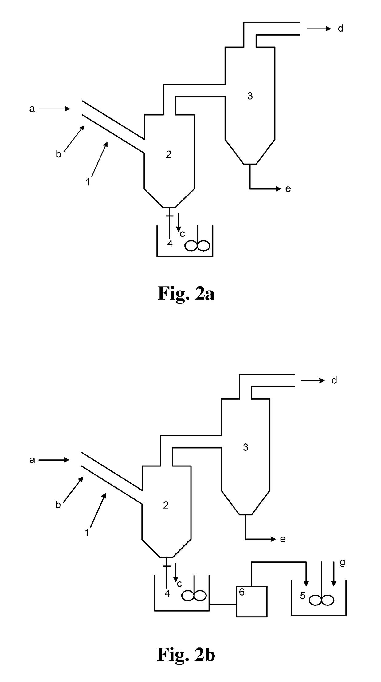
[0195]A molecular sieve gas-phase silicon insertion apparatus was made with a stainless steel of NiCr18Ti in a thickness of 3 mm according to FIG. 2a or 2b or FIG. 8. The upper part of the gas-solid separator 2 was a cylinder with a diameter of 6 meters and a height of 14 meters. The lower part was a cone with an opening. The cone had a cone angle of 45°. A valve was provided at the opening. The outlet was located at a position away from the top of the gas-solid separator by 1 meter. The absorber 3 held an aqueous sodium hydroxide solution (10 mol / L). The absorber 3 and the gas-solid separator 2 were communicated via a conduit, which was inserted into the aqueous sodium hydroxide solution.

[0196]The reactor 1 was a tube reactor, as shown in FIG. 5. The tube body had a total length of 80 meters. The tube body had a diameter of 0.8 meters. The tube body of the reactor was made in an annular shape. The reactor included the upper layer of straight tube and the lower layer of straight tub...

example 2

[0198]A molecular sieve gas-phase silicon insertion apparatus was made with a stainless steel of NiCr18Ti in a thickness of 3 mm according to FIG. 2a or 2b or FIG. 8. The upper part of the gas-solid separator 2 was a cylinder with a diameter of 6 meters and a height of 14 meters. The lower part was a cone with an opening. The cone had a cone angle of 45°. A valve was provided at the opening. The outlet was located at a position away from the top of the gas-solid separator by 1 meter. The absorber 3 held an aqueous sodium hydroxide solution (10 mol / L). The absorber 3 and the gas-solid separator 2 were communicated via a conduit, which was inserted into the aqueous sodium hydroxide solution.

[0199]The tube body of the tube reactor 1 had a length of 60 meters and was a straight tube. The angle between the axis of the tube body of the reactor and the horizontal plane was 45°. The tube body had an inner diameter of 1 meter. As shown in FIG. 3, the molecular sieve was conveyed by gravity. ...

example 3

[0201]A molecular sieve gas-phase silicon insertion apparatus was made with a stainless steel of NiCr18Ti in a thickness of 3 mm according to FIG. 2a or 2b or FIG. 8. The angle between the axis of the tube body of the reactor and the horizontal plane was 55°. The inner diameter of the tube body was 0.5 meter. The upper part of the gas-solid separator 2 was a cylinder with a diameter of 6 meters and a height of 14 meters. The lower part was a cone with an opening. The cone had a cone angle of 45°. A valve was provided at the opening. The outlet was located at a position away from the top of the gas-solid separator by 1 meter. The absorber 3 held an aqueous sodium hydroxide solution (10 mol / L). The absorber 3 and the gas-solid separator 2 were communicated via a conduit, which was inserted into the aqueous sodium hydroxide solution.

[0202]The gas-phase ultra-stabilization reaction apparatus was shown in FIG. 6. The molecular sieve was moved by gravity in the gas-phase ultra-stabilizati...


PUM

PropertyMeasurementUnit
temperatureaaaaaaaaaa
acute angleaaaaaaaaaa

Abstract

A process for preparing a catalytic cracking catalyst, which process comprises: a molecular sieve is introduced into a gas-phase ultra-stabilization reactor, the molecular sieve is moved without the conveying of carrier gas from a molecular sieve inlet of the gas-phase ultra-stabilization reactor to a molecular sieve outlet of the gas-phase ultra-stabilization reactor, and the molecular sieve is contacted and reacted with a gaseous SiCl4 in the gas-phase ultra-stabilization reactor, the molecular sieve resulting from the contacting and the reacting is optionally washed, then mixed with a matrix and water into slurry, and shaped into particles.

Description

TECHNICAL FIELD[0001]The present invention relates to a process and an apparatus for preparing a molecular sieve. The present invention also relates to a process for preparing a catalytic cracking catalyst.BACKGROUND[0002]The molecular sieve is a material widely used in the catalytic cracking catalyst, and is also an important component of the catalytic cracking catalyst. The property of the molecular sieve directly affects the reaction performance of the catalytic cracking catalyst. According to different demands, the molecular sieve can be modified in different ways so as to satisfy the use requirement. For example, a molecular sieve with a high silica-alumina ratio is generally considered as being required by the catalytic cracking catalyst.[0003]In the preparation of a molecular sieve with a high silica-alumina ratio, there are the following processes: dealumination and silicon insertion with ammonium hexafluorosilicate, hydrothermal dealumination and silicon insertion, and gas-...

Claims


Application Information

Patent Timeline
Patent Type & Authority Patents(United States)
IPC IPC(8): B01J29/08B01J37/00B01J29/06B01J37/06B01J37/04
CPCB01J29/088B01J29/06B01J37/0063B01J37/0072B01J37/06B01J37/04B01J2229/42B01J2229/12B01J2229/16B01J2229/32
Inventor XU, MINGDEZHANG, JIEXIAOZHOU, LINGPINGZHANG, WEILINTIAN, HUIPINGZHU, YUXIA
Owner CHINA PETROCHEMICAL CORP
Learn More