Free form fracturing method for electronic or optical lithography using resist threshold control

a free-form fracturing and threshold control technology, applied in the field of electronic or optical lithography of masks, can solve the problems of increasing the cost of masks or wafers, increasing the cost of production, and reducing so as to minimize the roughness of the free-form contour, reduce the number of shots, and improve the robustness to the fluctuations of the process

Inactive Publication Date: 2018-02-13
ASELTA NANOGRAPHICS
View PDF10 Cites 0 Cited by
  • Summary
  • Abstract
  • Description
  • Claims
  • Application Information

AI Technical Summary

Benefits of technology

[0010]It is an object of the present invention to provide a solution to this problem by taking account of the dose level resulting in a definite area of the target design from the proximity effect created by a first series of shots to determine the threshold of the exposure level of a second series of shots.
[0018]Advantageously, a degree of overlap between the rounded shot prints determined by the shots in the first and second sets of shots is set at a level which is determined based on a criteria combining at least minimization of roughness of a printed contour of the shot prints and a minimization of the shot count.
[0027]In certain embodiments, a predetermined roughness tolerance level can be complied without using any overlapping shots. In certain embodiments, the invention provides a significant reduction of the number of shots which are needed to minimize the roughness of the contour of the free form. Also, the method of the invention offers better robustness to the fluctuations of the process, because of the overexposure used in preferred embodiments. Because the number of shots is reduced in relation to the prior art, the size of the dataprep file is reduced.

Problems solved by technology

Under these circumstances traditional fracturing is not advantageous because it generates a very high number of shots, especially when pattern fidelity is critical.
The writing time increases proportionally to the number of shots, which in turns increases significantly the cost of producing masks or wafers.
But this prior art document does not properly address the problem of controlling the roughness of the contour of the free form which is actually exposed and the exposure dose.

Method used


Image

  • Free form fracturing method for electronic or optical lithography using resist threshold control
  • Free form fracturing method for electronic or optical lithography using resist threshold control
  • Free form fracturing method for electronic or optical lithography using resist threshold control

Examples


Embodiment Construction

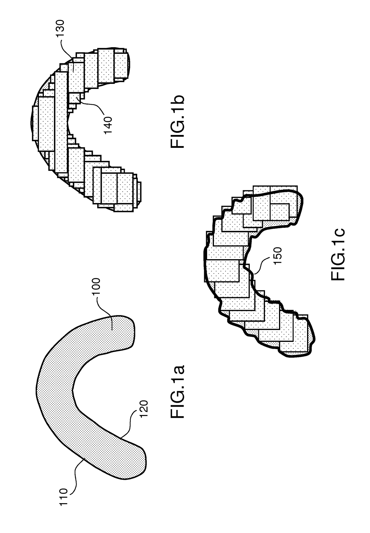
[0041]FIGS. 1a, 1b and 1c illustrate a method of the prior art to fracture a free form target design.

[0042]A curvilinear form 100, having brims 110, 120 can be insulated using a series of shots 130, 140, which can be deemed at the dimensions which are discussed in the framework of this invention (for instance a critical dimension or CD in the region of around 60-80 nm) to create a circular imprint (see below). Typically, the form 100 and the largest shots 130 will have a width of around 200 nm. If the shots do not overlap, like on FIG. 1b, the brims of the curvilinear form will have significant roughness at the loci in between two successive, tangential, shots. Allowing two successive shots to overlap, like on FIG. 1c, will alleviate a bit the problem, as can be seen in the areas of the curvilinear form where the curve radius is infinite. But where the curve radius is small, like at loci 150, the overlap will procure an excessive dose and the brim will be uneven, which will affect t...


PUM

PropertyMeasurementUnit
widthaaaaaaaaaa
diameteraaaaaaaaaa
diameteraaaaaaaaaa

Abstract

A computer implemented method of fracturing free form target design into elementary shots for defined roughness of the contour comprises determining a first set of shots which pave the target design and determining a second set of shots to fill the gaps. The dose levels of overlapping shots in the first or second sets of shots are determined so the compounded dose is adequate to the resist threshold, considering the proximity effect of the actual imprint of shots on the insulated target. A dose geometry modulation is applied and rounded shot prints are produced by shots not circular that may overlap. The degree of overlap is determined as a function of desired optimization of fit criteria between a printed contour and the contour of the desired pattern. Placements and dimensions of the shots are determined by a plurality of fit criteria between printed contour and contour of the desired pattern.

Description

CROSS-REFERENCE TO RELATED APPLICATIONS[0001]This application is a National Stage of International patent application PCT / EP2014 / 072948, filed on Oct. 27, 2014, which claims priority to foreign European patent application No. EP 13306483.2, filed on Oct. 30, 2013, the disclosures of which are incorporated by reference in their entirety.FIELD OF THE INVENTION[0002]The present invention notably applies to the field of electronic or optical lithography of masks for transferring designs on to a substrate. It also applies to processes whereby an electron beam is used to directly write a pattern on a substrate or mask.BACKGROUND[0003]One way of transferring a pattern on to a surface by e-beam lithography is to use a variable shaped beam or VSB to reveal a positive or negative resist coating. For doing so, during a fracturing step, the pattern is to be cut into elementary forms to which a radiation dose is assigned (known as “shots”). Geometry and radiation dose of the shots are closely in...

Claims


Application Information

Patent Timeline
Patent Type & Authority Patents(United States)
IPC IPC(8): G06F17/50H01J37/317G03F7/20G03F1/68H01J37/302G03F1/70
CPCG03F1/70G03F1/68G03F7/70433G06F17/5068H01J37/3026H01J37/3174G03F7/70558H01J2237/31776G06F30/39
Inventor MANAKLI, SERDARMARTIN, LUC
Owner ASELTA NANOGRAPHICS
Why Eureka
Try Eureka