Optical grating phase modulator for laser interference photoetching system

a laser interference photoetching and optical grating technology, applied in the field of optical grating phase modulator, can solve the problems of ghost lines present in processed gratings, poor precision in large-scale processing, and mechanical scratching, and achieve high phase modulation speed, wide modulation range, and high modulation precision

Active Publication Date: 2018-01-16
TSINGHUA UNIV
View PDF8 Cites 0 Cited by
  • Summary
  • Abstract
  • Description
  • Claims
  • Application Information

AI Technical Summary

Benefits of technology

[0008]One object of the present invention is to provide an optical grating phase modulator for phase modulation of a laser interference photoetching system, which has the advantages of high speed of phase modulation, high precision of phase modulation, and wide range of modulation. The phase modulation by the grating phase modulator does not influence the precision of system, the contrast ratio, and depth of focus and size of focal spot etc. of the system, and the optical path of the system is simple and clear, thereby improving the overall performance of the laser interference photoetching system.
[0013]The grating phase modulator for laser interference photoetching system of the present invention has the following advantages: the grating phase modulator has the advantages of high speed of phase modulation, high precision of modulation and wide range of modulation. When the grating phase modulator of present invention is applied in the laser interference photoetching system, it enable the system to have simple structure, and enable the system to achieve image locking of high speed and high precision without influencing the quality of image, thereby improving the overall performance of the laser interference photoetching system.

Problems solved by technology

The mechanical scratching has the disadvantages of poor precision in large-size processing, long periodical of processing, and ghost line present in processed gratings etc.
The laser direct writing has the disadvantages of poor precision in large-size processing and long periodical of processing etc.
The mechanical splicing has the disadvantages of poor precision of splicing, complicated splicing process and high cost etc.
Thus it is difficult to use these techniques to achieve the above mentioned quality.
The development of laser interference photoetching system is a major difficulty in laser interference photoetching applicable in manufacturing grating of large-size and high precision, and the development of laser interference photoetching system of high precision is really high technology.
One patent of MIT, i.e., U.S. Pat. No. 5,142,385 discloses a laser interference photoetching system which comprises a image locking device which performs image locking through phase modulation of beams with an electro-optic phase modulator, but the electro-optic phase modulator has the disadvantages of low speed of phase modulation, low precision of modulation and narrow range of modulation, which is difficult to meet the requirements for image locking of high precision.
Besides, the phase modulation by the acoustic-optic modulator may increase the complicatedness of optical path of the system.
Taking the above issues into consideration, the phase modulation by the acoustic-optic modulator may not be an optimal choice.
This method does not change the frequency of beams and does not influence the coherence characteristics of the exposing rays, but the change of the position of the reflector may influence the contrast ratio of image, and depth of focus and size of focal spot etc. of the system, and the driving of the optical reflector seat by piezoelectric ceramics has the disadvantages of low speed of modulation, low precision of modulation, and limited range of modulation, which is also difficult to meet the requirements of image locking of high speed and high precision.

Method used


Image

  • Optical grating phase modulator for laser interference photoetching system
  • Optical grating phase modulator for laser interference photoetching system
  • Optical grating phase modulator for laser interference photoetching system

Examples


Embodiment Construction

[0021]The embodiments of the present invention will be described in further detail with reference to the drawings.

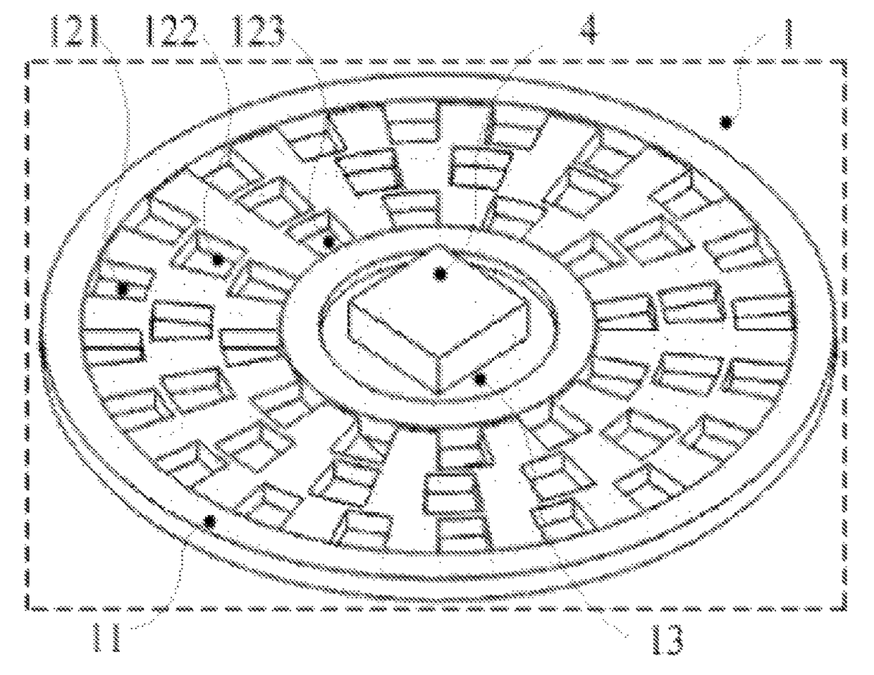
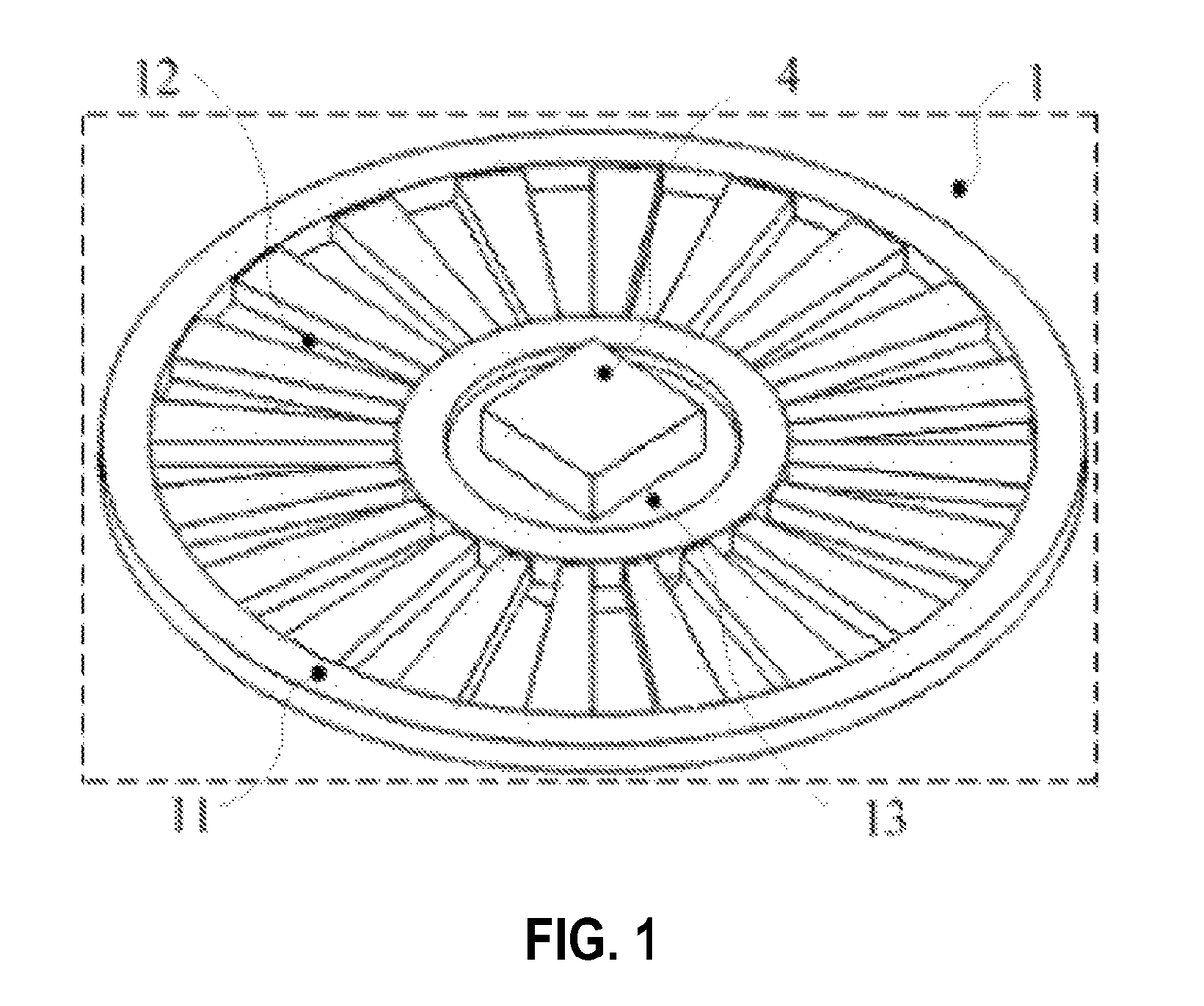
[0022]Referring to FIG. 1, FIG. 1 illustrates the structure of a first circular grating phase modulator of the present invention. As shown in FIG. 1, the circular grating phase modulator 1 comprises a circular base plate 11, a circular grating 12, a rotary motor 13 and a grating positioner 4. The circular grating 12 is mounted on the circular base plate 11 in a peripheral direction, and only one circular grating is mounted in the first circular grating phase modulator (the pitch of the grating is enlarged in the Figure for clarity). The output shaft of the rotary motor 13 is coupled to the circular base plate 11, and the grating positioner 4 is mounted on the circular base plate 11.

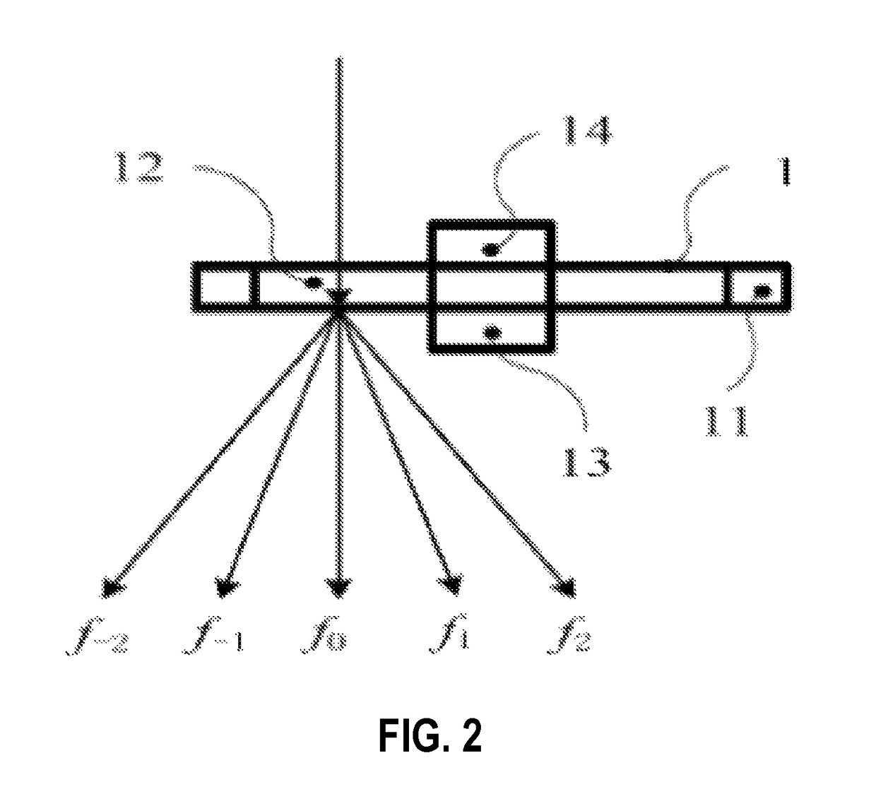
[0023]Referring to FIG. 2, FIG. 2 illustrates the principle of a circular transmission grating phase modulator. As shown in FIG. 1, the circular grating 12 is a transmission grating, and diffr...


PUM

PropertyMeasurementUnit
grid densityaaaaaaaaaa
grid densitiesaaaaaaaaaa
frequenciesaaaaaaaaaa

Abstract

An optical grating phase modulator for a laser interference photoetching system is composed of a substrate, an optical grating, an electric motor and an optical grating positioner. The optical grating, the electric motor and the optical grating positioner are all mounted on the substrate. The optical grating is circular or rectangular, and adopt transmission or reflection type optical grating. A light beam is incident on the optical grating and generates diffraction, and when the electric motor drives the optical grating to continuously move relative to the incident light beam, diffracted light will generate a frequency shift, thereby realizing the phase modulation of the light beam. The optical grating phase modulator has the advantages of high phase modulation speed, high regulation precision and wide regulation range, thereby improving the whole performance of an interference photoetching system.

Description

CROSS-REFERENCE TO RELATED APPLICATIONS[0001]This application is a National Stage of International Patent Application No. PCT / CN2014 / 070521, entitled “OPTICAL GRATING PHASE MODULATOR FOR LASER INTERFERENCE PHOTOETCHING SYSTEM” and filed on 13 Jan. 2014, which takes priority from Chinese Patent Application 201310017800.X filed on 17 Jan. 2013, all of which are incorporated herein by reference in their entirety.TECHNICAL FIELD[0002]The present invention relates to an optical grating phase modulator, particularly, to an optical grating phase modulator for phase modulation in a laser interference photoetching system.BACKGROUND ART[0003]Laser interference photoetching is an important method of manufacturing micro or nano-scale array device by exposing a photosensitive substrate using periodical diagram generated by interference between two or more laser beams. This photoetching technology is mainly applied in manufacturing devices which has a feature size lower than subwavelength such as...

Claims


Application Information

Patent Timeline
Patent Type & Authority Patents(United States)
IPC IPC(8): G02B26/00G02B5/18G02B26/06G03F7/20
CPCG02B26/06G03F7/70408G03F7/70316G03F7/20
Inventor ZHU, YUZHANG, MINGWANG, LEIJIECHENG, RONGYANG, KAIMINGLIU, ZHAOHU, JINCHUNYIN, WENSHENGMU, HAIHUAHU, CHUXIONGXU, DENGFENG
Owner TSINGHUA UNIV
Why Eureka
Try Eureka