
Electrode boiler with electrodes unit

a technology of electrodes and boilers, applied in the field of heat engineering and power engineering, can solve the problems of reducing the overall efficiency of the electrode system at a rather high rate, reducing the fabricability of the device, the electrodes, and the impediment to the intended function of the boiler, etc., to improve the design reliability, improve the service life of the device, and improve the overall efficiency of the electrode system. , the effect of improving the service li

Active Publication Date: 2017-12-12
KIM NO EUL
View PDF121 Cites 0 Cited by
  • Summary
  • Abstract
  • Description
  • Claims
  • Application Information

AI Technical Summary

Benefits of technology

This invention aims to make it easier to making and work with multiple electrodes and boilers. It also improves the reliability and design of the device, ensures it's compatible with various operating conditions, increases its lifespan, and makes it easier to maintain and repair. Additionally, it enhances the performance and flexibility of the device, and reduces issues like sludge and rust deposition. This invention also protects against breakdowns, reduces phase current load imbalance, and ensures the electrodes are always protected during operation. It also extends the range of constructional capacity control without design and dimensional changes.

Problems solved by technology

Among general disadvantages of electrode boilers the geometrically symmetric arrangement of electrodes inside the case, relative to each other, normally in parallel with the longitudinal axes and symmetry axes of the boiler case can be pointed out, which reduces considerably the fabricability of the devices, electrodes, complicates assembly, repair works, and cleaning as the latter can disturb the said symmetry.
Besides, such a manner of electrode in-case fastening does not allow flexible purposive changing of convection conditions for liquid flows of different temperatures within the boiler thus impeding the mixing or separation subject to the boiler intended function.
In addition, the strictly symmetric arrangement of electrodes creates favourable conditions for uniform deposition of iron oxidation products (rust Fe (OH)2) and foreign particles suspended in the fluid (sludge), which reduces the overall efficiency of electrode system at a rather high rate.

Method used


Image

  • Electrode boiler with electrodes unit
  • Electrode boiler with electrodes unit
  • Electrode boiler with electrodes unit

Examples


embodiment 1

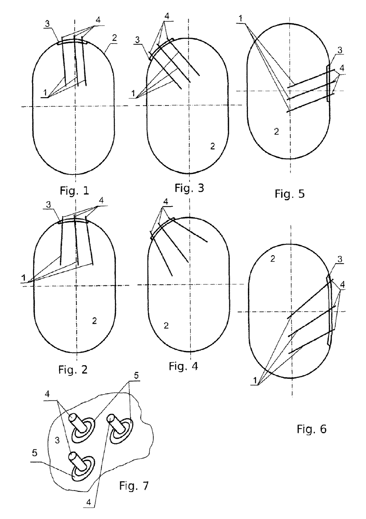
[0063]FIGS. 1 . . . 7, 14 . . . 28 represent a view of configuration of electrode boiler with multiple electrode according to Embodiment 1 of this invention.

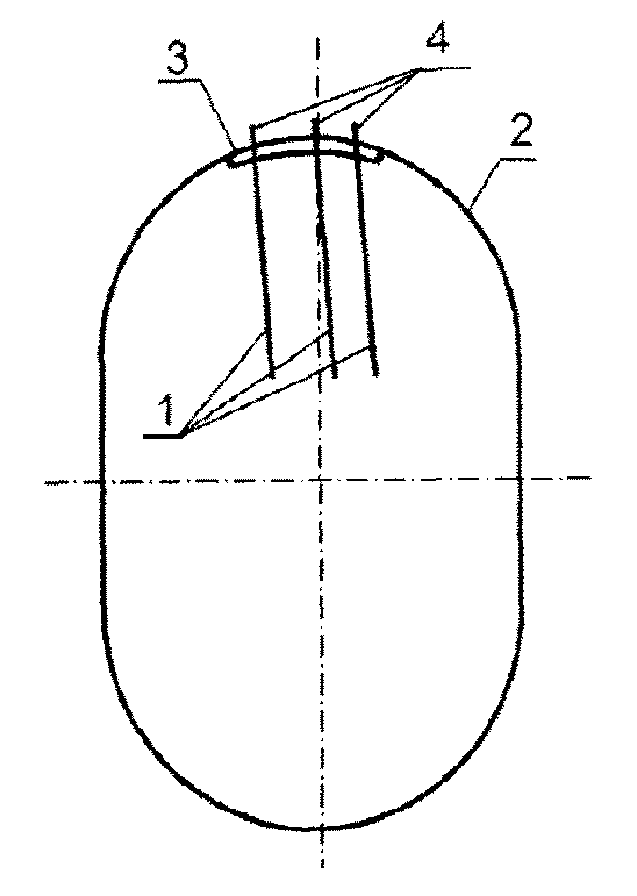
[0064]As per Embodiment 1, electrodes 1 of the device, at least one or more electrodes are directed inside the case 2 downwards. In FIG. 1, electrodes 1 are directed straight down, the longitudinal axes of all the electrodes 1 slightly deviating from the longitudinal symmetric axis of case 2. Electrodes 1 if used more than one in number may be installed at different unequal distances to each other (FIG. 1). Longitudinal axes of part or of all electrodes 2 may also form nonzero angles against each other as shown in FIG. 2 accompanied by unequal distances between electrodes 1. Electrodes 1 are located at basis 3 which may be installed both inside case 2, as shown in FIGS. 1-2, 5-6, and outside—FIGS. 3-4. Each electrode 1 has terminal 4 running through basis 3 and case 2 to be connected to an electric power supply. Basis 3 may be i...

embodiment 2

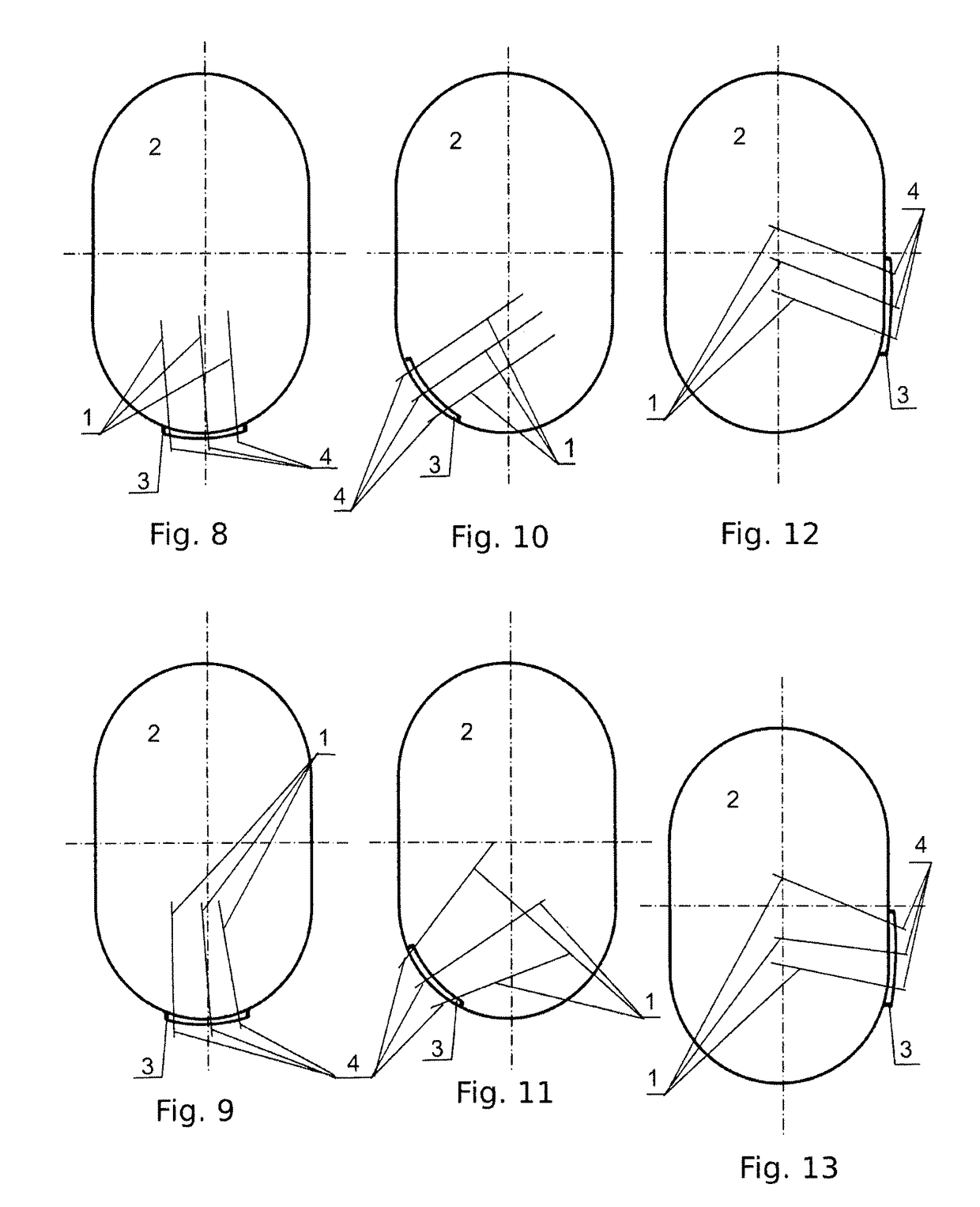
[0073]FIGS. 8-28 represent a view of electrode boiler with multiple electrode configuration according to Embodiment 2 of the invention in question. Embodiment 2 has the following specific aspects as compared to Embodiment 1.

[0074]As per Embodiment 2, electrodes 1 of the device, at least one electrode or more, for example two or three for a three-phase electric mains, or in number multiple of 3 for a three-phase electric mains—are directed into case 2 upwards. In FIG. 8 electrodes 1 are directed upwards vertically with the longitudinal axes of all electrodes 1 slightly deviating from the longitudinal symmetric axis of case 2. Electrodes 1, if used in number exceeding one, may be installed at different unequal distances from each other (FIG. 8). The longitudinal axes of electrodes may also make non-zero angles against each other for all electrodes 2 or a part of them as shown in FIG. 9; this being accompanied with unequal distances between electrodes 1 at the same time. Electrodes 1 a...

embodiment 3

[0079]FIGS. 29-36 represent a view of configuration of an electrode boiler with multiple electrode according to Embodiment 3 of this invention. Embodiment 3 has the following specific aspects as compared to Embodiments 1 and 2.

[0080]As per Embodiment 2, electrodes 1 of the device, at least one electrode or more, for example two or three for a three-phase electric mains, or in number multiple of 3 for a three-phase electric mains, or in any required number, generally all used in a concrete specimen of the device, are fastened directly in case 2 without any basis. Such an implementation of the device provides (FIG. 29) fastening of electrodes 1 through dielectric insulating heat-resistant inserts 5 directly pressed into the wall of case 2 or its cover. Here, terminals 4 of electrodes 1 for connection of an electric power supply are brought outside from the device case 2.

[0081]Electrodes 1 may be grouped at the same point of boiler case similarly to Embodiments 1, 2 or distributed on t...


PUM


Abstract

The invention relates to heat engineering, power engineering and the field of electric heating of liquids, water for instance; it can be used in circulation water heating systems and hot water supply, and as a universal device for diverse electric heaters. An object of the invention are to enhance the ease of fabrication, fabricability, and operability for block electrodes and electrode heating boilers on the whole, to increase the reliability of device both in static and dynamic modes ones. The invention meets an object of extended performance capabilities, versatility and flexibility of the device, potential diversification and enhancement of adaptability in solving particular problems. Moreover, the invention allows improvement of convection in water heating boilers and reduction of uniformity of sludge and rust deposition on electrodes thus increasing the heater effective performance time. The invention object comprises an improvement of protection against breakdowns between the electrodes as well, phase current load imbalance reduction, electrode protection against non-uniform deformation during operation in dynamic conditions. It is also an object of the invention to extend i the range of constructional capacity control without design and dimensional changes. FIG. 2 provides a schematic of electrodes (1) arrangement on the basis (3) located on the inner case (2) side with electrodes (1) slightly deviating from the longitudinal symmetric axis of the case (2) and irregularly spaced on the basis, electrode longitudinal axes deviating from each other at small angles. (4)—outer electrode terminals (1).

Description

FIELD OF THE INVENTION[0001]The invention relates to heat engineering, power engineering and the field of electric heating of liquids, water for instance, steam generation, direct conversion of electric energy into heat energy; it can be used in circulation water heating systems, self-regulating liquid heaters for autonomous heating and hot water supply, mobile heating and hot water supply, and as a universal device for diverse electric heaters.BACKGROUND OF THE INVENTION[0002]Electrode water heating boilers are designed to provide hot water and steam at the expense of heat released by electric current (single- or three-phase one) directly flowing through water. Boilers are used for heating and hot water supply of production and residential spaces, in open as well as close heating systems. They are also used at industrial plants, agricultural plants, and any other facilities which manufacturing processes require hot water of 95 . . . 100 Celsius degrees. The simple design, high reli...

Claims


Application Information

Patent Timeline
Patent Type & Authority Patents(United States)
IPC IPC(8): F22B1/30H05B3/03H05B3/02H05B3/60F24H9/18F24H9/00F24H1/20
CPCF22B1/30F24H1/203F24H9/0047H05B3/023H05B3/03H05B3/60F24H9/1818F24H2250/10H05B3/0009F24H9/455
Inventor ILIN, ANDREY PAVLOVICH
Owner KIM NO EUL
Learn More