
Smart balance wheel with bolt-shaft structure

a bolt-shaft and balance wheel technology, applied in the field of two-wheel balance wheels, can solve the problems of high cost of products, poor safety performance, operability and economic efficiency, and insufficient structural efficiency, and achieve the effects of convenient operation, high safety performance, and economic manufacturing cos

Inactive Publication Date: 2017-12-12
GUANGDONG LONGXIN TECH CO LTD
View PDF2 Cites 35 Cited by
  • Summary
  • Abstract
  • Description
  • Claims
  • Application Information

AI Technical Summary

Benefits of technology

The present invention aims to provide a smart balance wheel with a bolt-shaft structure having high safety performance, easy operation, economic manufacturing cost and providing human riding and fitness. The balance control and drive system is operated by the driver to control and drive, and only when the driver stands on the wheel body and forms an angle of inclination, the motor can be started to improve the safety performance of the driver. The connection between the left and right frames is safer and more secure, with a screw and nut that are easily fixed with less working time. The frames are safer and more stable, with a spacing boss and a spacing hole that reduces the risk of accidents. The balance control and drive system have an auxiliary control board, positioning frames, and sensing rubber mat that form a closed dustproof structure, improving safety, service life and stability.

Problems solved by technology

However, the present patent technology and related product have bad safety performance, operability and economic efficiency, high cost of the product, or insufficient structural efficiency, or are too heavy to carry, or insensitive to use with low safety and operability, even with fall damage.

Method used


Image

  • Smart balance wheel with bolt-shaft structure
  • Smart balance wheel with bolt-shaft structure
  • Smart balance wheel with bolt-shaft structure

Examples


Embodiment Construction

[0031]The specific embodiment of the present invention is further illustrated according to the accompanying drawings.

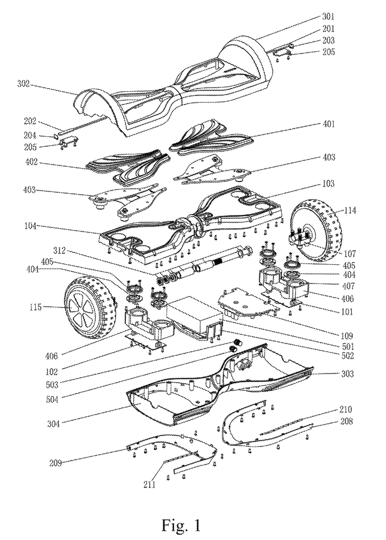
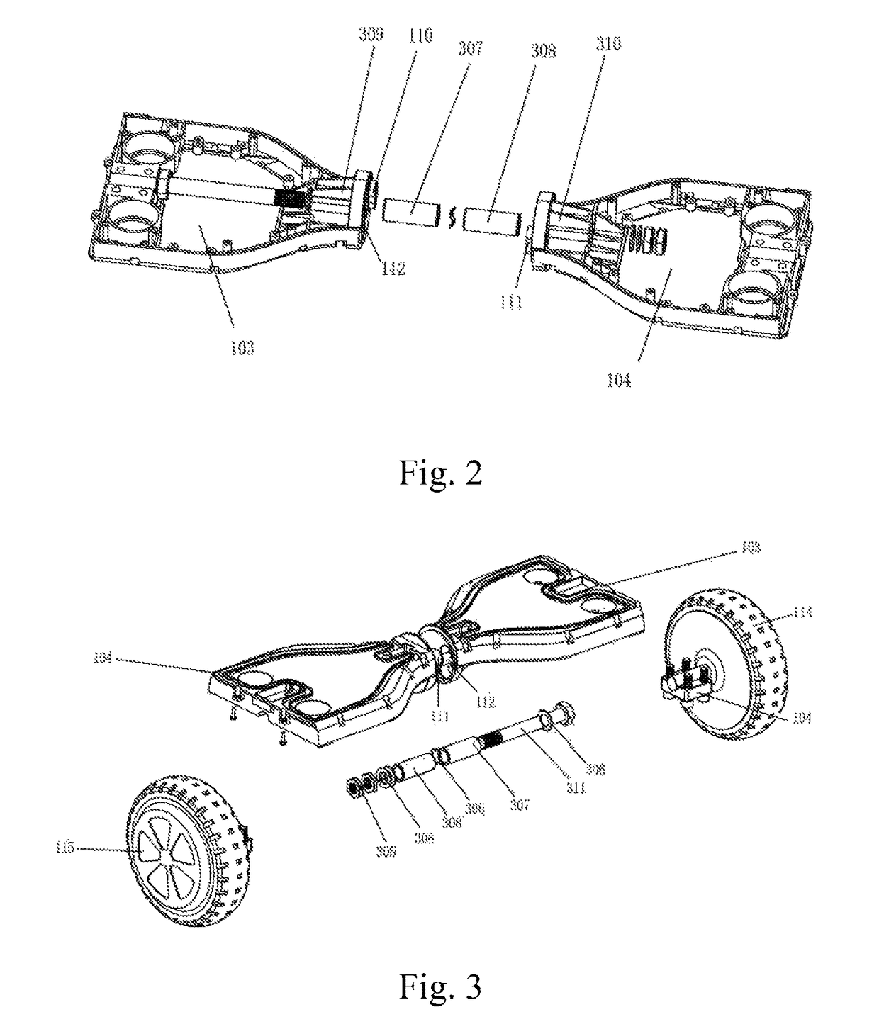
[0032]Referring to FIGS. 1-4:

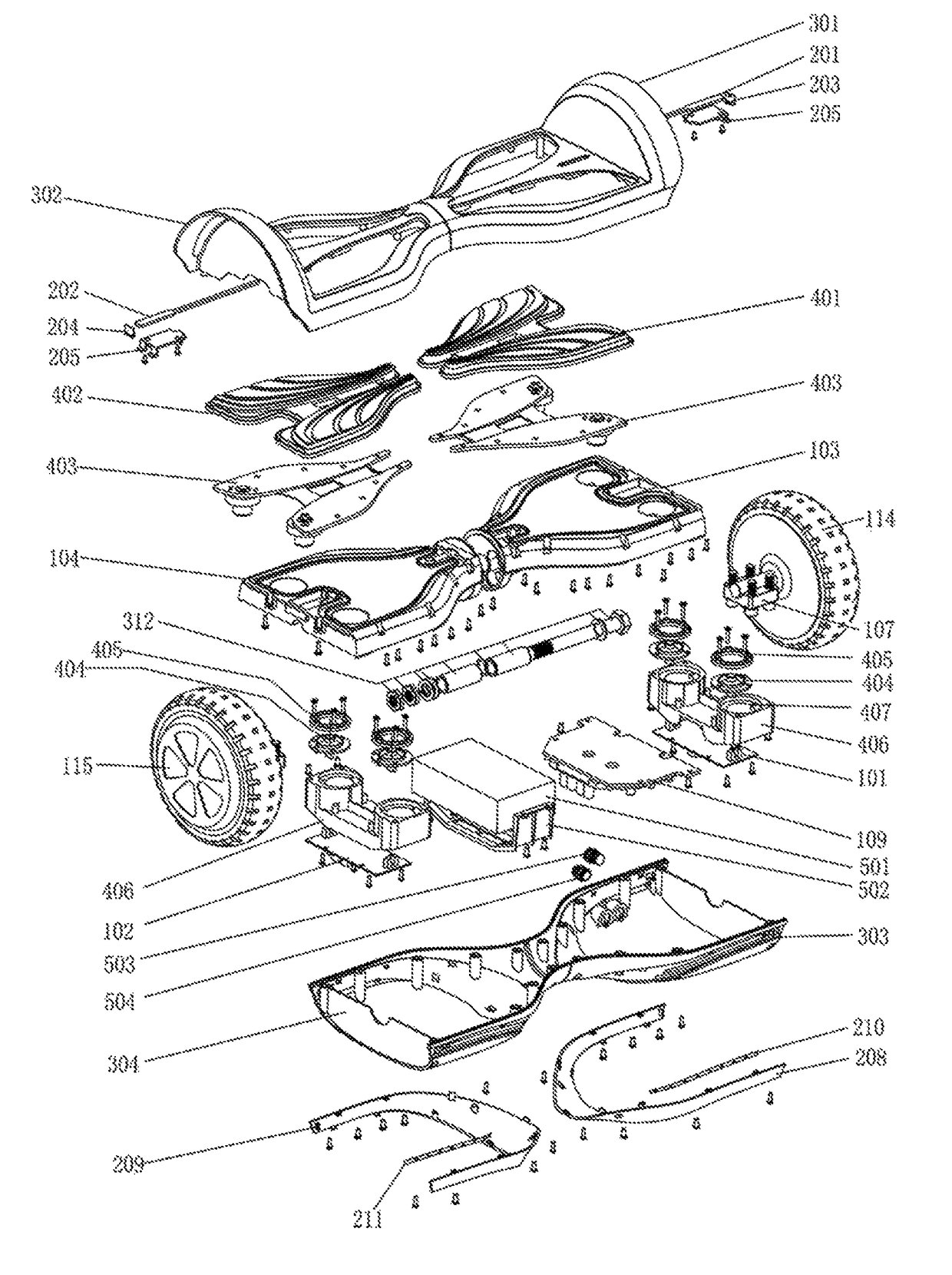
[0033]A smart balance wheel with a bolt-shaft structure includes a fixedly connected bearing and shaft system. The fixedly connected bearing and shaft system includes a main frame and a shaft system. The main frame includes a left frame 101 and a right frame 102 symmetric to each other and rotating relative to each other. A left drum 309 and a right drum 310 are disposed on the opposite sides of the left frame 101 and the right frame 102, respectively. The shaft system passes through the left drum 309 and the right drum 310 to realize relative rotation of the left frame 103 and the right frame 104. A left spacing boss 110 and a left spacing through hole 112 are formed inside the left drum 309, and a right spacing boss 111 and a right spacing through hole 113 are formed inside the right drum 310. The left spacing boss 110 moves within the r...


PUM


Abstract

The present invention discloses a smart balance wheel with a bolt-shaft structure, comprising a fixedly connected bearing and shaft system, a balance control and drive system, a safety control and prompt system and a charging system. The fixedly connected bearing and shaft system comprises a main frame and a shaft system. The main frame comprises a left frame and a right frame symmetric to each other and rotating relative to each other. The shaft system passes through the left and right frames to realize relative rotation. The balance control and drive system is located under the fixedly connected bearing and shaft system. The present invention uses a bolt-shaft structure and a closed dustproof structure, realizes fixing of the left and right main frames, increases connection strength and bearing capacity of the frame, improves safety of balancing, controlling and driving and improves the service life.

Description

BACKGROUND OF THE INVENTION[0001]Technical Field[0002]The present invention belongs to the manufacturing field of two-wheel balance wheel, and particularly to a smart balance wheel with a bolt-shaft structure.[0003]Description of Related Art[0004]The balance wheel gradually gets attention and affection of the youth because of its convenient carrying, simple operation and good stability. The subject of patent application for the balance wheel is currently from Hangzhou Chic Intelligent Technology Co. Limited, Segway LLC., and CHENHE. However, the present patent technology and related product have bad safety performance, operability and economic efficiency, high cost of the product, or insufficient structural efficiency, or are too heavy to carry, or insensitive to use with low safety and operability, even with fall damage. The present invention increases the carrying capacity and has sensing parts of the balance wheel that are not easy to be polluted and damaged by promoting innovati...

Claims


Application Information

Patent Timeline
Patent Type & Authority Patents(United States)
IPC IPC(8): B62K11/00B60L11/18B60K1/02B60Q1/50
CPCB62K11/007B60Q1/50B60L11/1809B60K1/02B60K1/04B60K7/0007B60K2007/0038B60K2007/0092B60Y2200/112B60Y2200/126B60Y2200/81B60L53/00Y02T10/70Y02T10/7072Y02T90/14
Inventor ZENG, YONGFULIAO, LIANGMAOGAN, AGAN
Owner GUANGDONG LONGXIN TECH CO LTD
Learn More