
Sensor guard for using internal lens cleaning bulb blower on digital reflex camera, and method of use thereof

a technology of digital reflex camera and sensor guard, which is applied in the direction of cleaning process and apparatus, camera body details, instruments, etc., can solve the problems of increasing the danger of accidental damage of expensive fragile camera components, difficult to see clearly in the camera lens chamber, and high cost of digital reflex camera components. , to achieve the effect of preventing accidental short circui

Inactive Publication Date: 2017-10-17
1317442 ALBERTA
View PDF17 Cites 0 Cited by
  • Summary
  • Abstract
  • Description
  • Claims
  • Application Information

AI Technical Summary

Benefits of technology

The patent describes a connector means for a camera lens base and a cup means. The connector means consists of a semi-flexible spring-loaded wire that spirals into a hemispherical shape open wire cone. The wire has an elbowed inner end and is designed to interlock with the camera lens mount ring. The cup means is integrally mounted to the wire cone and is made of a frusto-conical extension of the wire with two sections. The wire can be coated with a non-conductive soft plastic material sheath to prevent accidental wire short circuiting. This design provides a flexible and secure connection between the camera lens base and the cup means, which can withstand high force impacts and vibrations during use.

Problems solved by technology

Components of digital reflex cameras are expensive and fragile, in particular lenses and mirrors inside the camera inner chamber located between the front standard lens and the rear pressure plate on the camera body hinge access door.
In such an environment, the camera lens chamber has dark corner areas that are difficult to see clearly because ambient light has limited access therein.
Therefore, it is a current problem to properly clean the whole volume of the camera sensor chamber, while avoiding accidental damage to fragile components thereof.
Moreover, due to the shifting demographic environment, another problem is that older users become frail and / or suffer from neuromuscular degenerative diseases such as Parkinson disease, and their dexterity will become compromised, thus increasing the hazards of accidentally damaging expensive fragile camera components during self-cleaning operations.

Method used


Image

  • Sensor guard for using internal lens cleaning bulb blower on digital reflex camera, and method of use thereof
  • Sensor guard for using internal lens cleaning bulb blower on digital reflex camera, and method of use thereof
  • Sensor guard for using internal lens cleaning bulb blower on digital reflex camera, and method of use thereof

Examples


Embodiment Construction

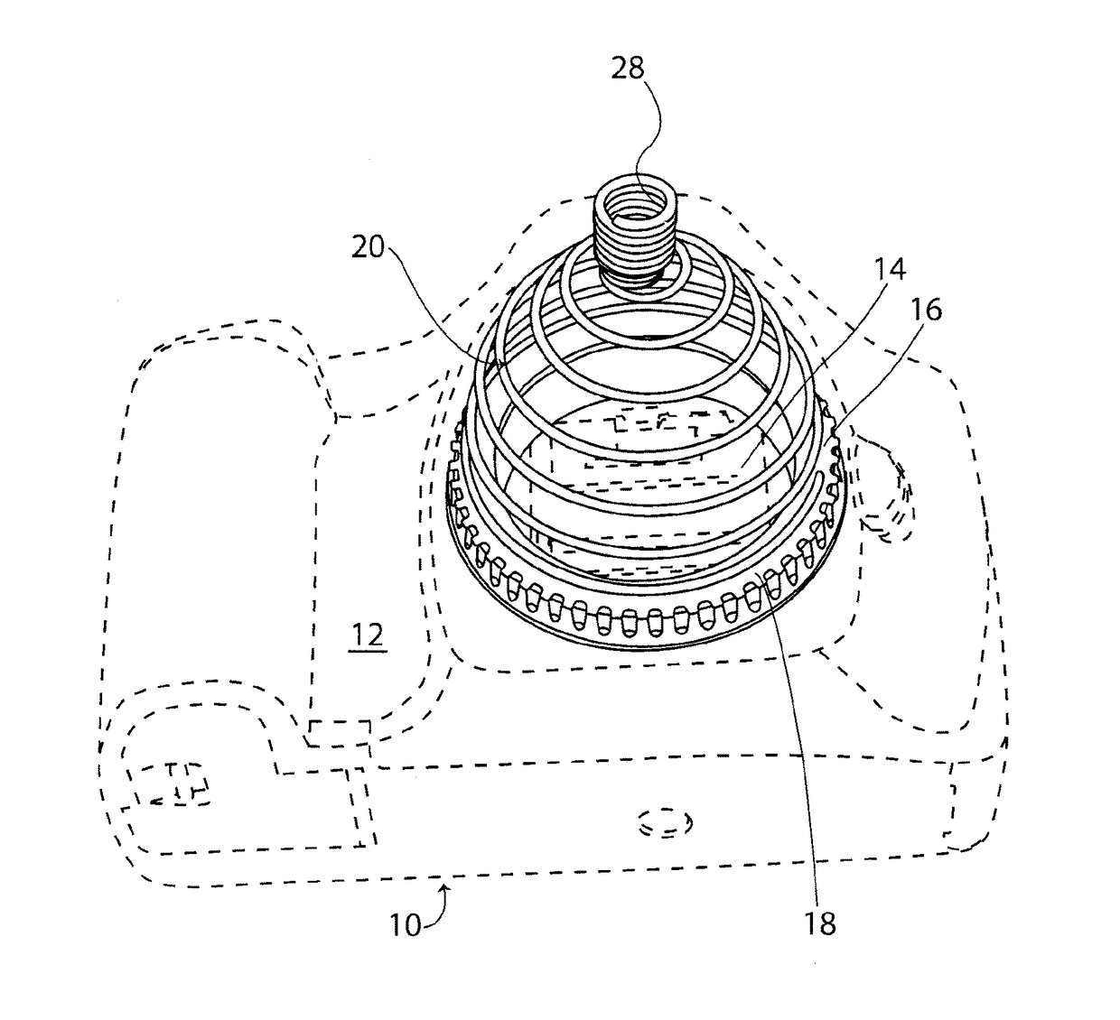
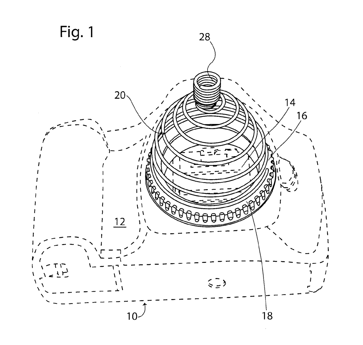
[0027]In FIG. 1, there is disclosed a digital reflex type camera 10 with the front standard lens removed and defining a main frame 12 with a camera lens inner chamber 14 accessible through a rear aperture 16. An exposed metallic ring 18 fixedly surrounds aperture 16.

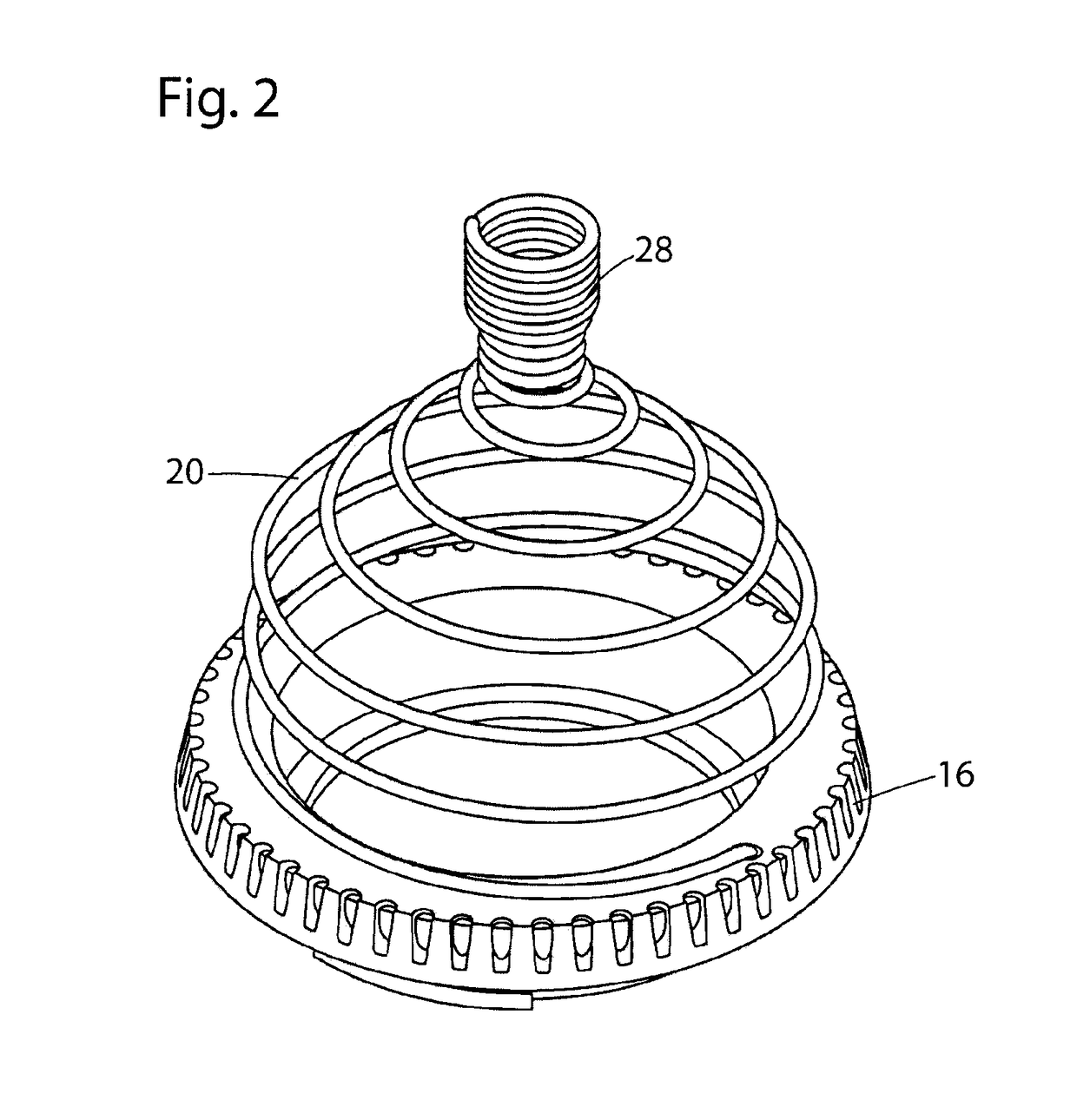
[0028]As illustrated in FIGS. 1 to 9, according to the first two embodiments of the invention, there is provided an open generally hemispheric sensor guard 20, 120. In the first embodiment of FIGS. 1 to 8, guard 20 is formed by a conical spiralling wire 22, defining a diametrally widest bottom annular wire segment 22A sized and shaped to fit flatly over camera lens bayonet mount ring 18, and a top diametrally smaller apex section 22B. Wire top apex section 22B is of frusto-conical shape, defining a diametrally smaller tubular inner section 24, and a diametrally larger tubular outer section 26, each wire sections 24, 26, consisting of at least a few spirals of wire 22. Outer apex wire section 26 forms a top free end expos...


PUM


Abstract

A cleaning apparatus for removing dust from lens surfaces inside a camera inner chamber, comprising: a bulb blower, a retainer is defined with a planar annular section, for fitting over a bayonet mount ring from the camera, a frusto-conical bottomless cup sized such that the blower nozzle outlet tip and main body are releasably engaged therethrough and the nozzle inlet seat releasably lockingly abuts thereagainst, and omnidirectional spring loaded connectors spacedly interconnecting the annular section to the cup, enabling the cup to move from a first position, at rest spacedly away from the plane of the retainer annular section, to a second position about the annular section plane. the nozzle outlet tip is progressively movable through the plane of the annular section against the bias of the connectors.

Description

CROSS-REFERENCE DATA[0001]The present application claims conventional priority of American provisional application No. 61 / 860,535 filed Jul. 31, 2013.BACKGROUND OF THE INVENTION[0002]Components of digital reflex cameras are expensive and fragile, in particular lenses and mirrors inside the camera inner chamber located between the front standard lens and the rear pressure plate on the camera body hinge access door. Sensor surfaces inside such camera's chamber needs to be periodically cleaned. Usually, such cleaning is performed with the camera supported over ground, with the recess of the camera inner chamber facing downwardly so that dust that is removed be able to fall downwardly under gravity from the chamber recess. In such an environment, the camera lens chamber has dark corner areas that are difficult to see clearly because ambient light has limited access therein. Therefore, it is a current problem to properly clean the whole volume of the camera sensor chamber, while avoiding...

Claims


Application Information

Patent Timeline
Patent Type & Authority Patents(United States)
IPC IPC(8): G02B27/00G03B17/56B08B5/02
CPCG02B27/0006B08B5/02G03B17/568G03B17/56
Inventor RAHBAR-DEHGHAN, FARIBORZ
Owner 1317442 ALBERTA
Learn More