Double balanced mixer

a mixer and double-balance technology, applied in the field of electronic circuits, can solve the problems of slow rate versus lo power increase of the third-order input-referenced intercept point (iip3) value, rapid decrease of the conversion gain (cg), and inability to use more than one diode per branch for linearity improvement, etc., to achieve good conversion gain and iip3 values, improve linearity, and wide bandwidth

Active Publication Date: 2017-10-03
PSEMI CORP
View PDF2 Cites 9 Cited by
  • Summary
  • Abstract
  • Description
  • Claims
  • Application Information

AI Technical Summary

Benefits of technology

[0011]The present invention provides a field effect transistor (FET) based double balanced mixer (DBM) that exhibits good conversion gain and IIP3 values and provides improved linearity and wide bandwidth.

Problems solved by technology

A problem with conventional diode DBMs is that their conversion gain (CG) rapidly decreases as LO power decreases, due to the turn-on voltage of the diodes.
The diode turn-on voltage also makes it impractical to use a diode ring with more than one diode per branch for linearity improvement, due to the large LO drive signal that would be required.
Another problem with conventional diode DBMs is that their third-order input-referenced intercept point (IIP3) value increases at a slow rate versus LO power.

Method used


Image

  • Double balanced mixer
  • Double balanced mixer
  • Double balanced mixer

Examples


first embodiment

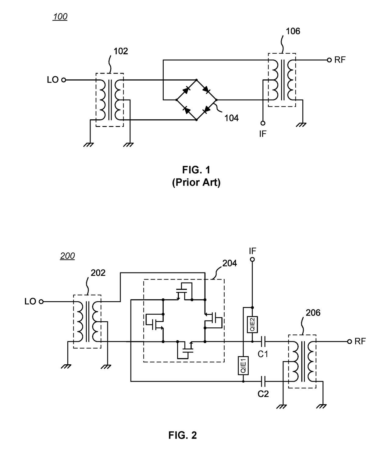
[0026]FIG. 2 is a schematic diagram of a first embodiment of a FET-based double balanced mixer 200 in accordance with the present invention. A first balun 202 is configured to receive a local oscillator (LO) signal on the unbalanced side and generate two balanced LO output signals that are coupled to two corresponding opposing nodes of a four-node FET ring 204. A second balun 206 is configured to pass a radio frequency (RF) signal on the unbalanced side of the second balun 206. The two legs of the balanced side of the second balun 206 are coupled to the remaining two opposing nodes of the FET ring 204 through DC-blocking capacitors C1, C2 which provide isolation between the RF and intermediate frequency (IF) signal ports. The first balun 202 and the second balun 206 may be external transformers, but are preferably integrally fabricated with the other circuitry on an IC, in known fashion.

[0027]In the illustrated embodiment, the IF signal port is coupled through quarter-wave isolation...

second embodiment

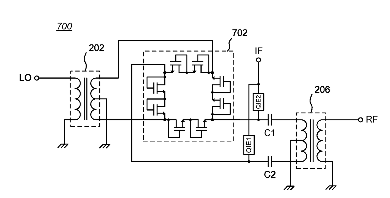
[0037]The linearity of a drain-gate connected FET-based DBM can be improved even further by using more than one drain-gate connected FET per branch of the four-node FET ring 204. For example, FIG. 7 is a schematic diagram of a second embodiment of a FET-based double balanced mixer 700 in accordance with the present invention, having two drain-gate connected FETs per branch of a four-node FET ring 702. More specifically, the FET ring 702 comprises four branches connected as a ring, with each branch including two drain-gate connected FETs (preferably low threshold voltage FETs); the circuitry is otherwise similar to the circuit shown in FIG. 2. The source of each drain-gate connected FET (indicated by an arrow in FIG. 7) is connected to the drain of a next drain-gate connected FET in the ring; the nodes of the FET ring 702 are between branches containing adjacent sets (pairs, in the illustrated configuration) of drain-gate connected FETs. While FIG. 7 shows two drain-gate connected FE...


PUM


Abstract

A FET based double balanced mixer (DBM) that exhibits good conversion gain and IIP3 values and provides improved linearity and wide bandwidth. In one embodiment, a first balun is configured to receive a local oscillator (LO) signal and generate two balanced LO signals that are coupled to two corresponding opposing nodes of a four-node FET ring. A second balun is configured to pass an RF signal on the unbalanced side. The FET ring includes at least four FETs connected as branches of a ring, with the source of each FET connected to the drain of a next FET in the ring. Each FET is preferably fabricated as, or configured as, a low threshold voltage device having its gate connected to its drain, which causes the FET to operate as a diode, but with the unique characteristic of having close to a zero turn-on voltage.

Description

BACKGROUND[0001](1) Technical Field[0002]This invention relates to electronic circuitry, and more particularly to radio frequency circuits.[0003](2) Background[0004]In electronics, a frequency mixer (or just “mixer”) is an electrical circuit that creates new frequencies from two applied signals. More particularly, in their simplest form, mixers are 3-port active or passive devices designed to yield both a sum and a difference frequency at a single output port when two distinct input frequencies are inserted into the other two ports. Thus, when two signals at frequencies f1 and f2 are applied to a mixer, the intended output is a product signal of the sum f1+f2 and difference f1−f2 of the original frequencies. In addition, the inputs to a mixer may be complex waveforms, such as a signal spectrum (e.g., in CDMA cellular telephone systems) or a broad spectrum of signals (e.g., cable TV). In practice, mixers also produce harmonic frequencies and higher order sum and difference frequencie...

Claims


Application Information

Patent Timeline
Patent Type & Authority Patents(United States)
IPC IPC(8): H03D7/02H01L21/84H01L29/786H01L29/78H01L27/092H01L21/86H01L27/06H01L23/66H03H7/42H03D7/14H01L21/8238H01L27/12
CPCH03D7/1458H03D7/1441H03H7/42H01L23/66H01L27/0629H01L27/1203H01L27/092H01L29/7838H01L29/786H01L21/84H01L21/86H01L21/8238H03D7/1408H03D7/02
Inventor SALAMEH, DAOUD
Owner PSEMI CORP
Why Eureka
Try Eureka