Separator, electrode element, electric energy storage device and method for producing separator

a technology of electric energy storage and separator, which is applied in the direction of electrochemical generators, cell components, cell component details, etc., can solve the problems of short circuit between positive and negative electrode plates over wide areas, short circuit between positive and negative electrode plates, etc., and achieve excellent ionic conductivity and yield improvement. , the effect of improving the yield

Active Publication Date: 2017-09-05
NEC CORP
View PDF33 Cites 2 Cited by
  • Summary
  • Abstract
  • Description
  • Claims
  • Application Information

AI Technical Summary

Benefits of technology

[0021]According to the present invention, it is possible to provide a separator, an electrode element and an electric energy storage device excellent in various performances in such a way that ionic conductivity is satisfactory, and the occurrence of the short-circuit between the electrodes in the electrode element and the electric energy storage device is extremely reduced. In the production process, the yield is improved and the handling is easy, and thus the productivity of the electrode element and the electric energy storage device can be improved.

Problems solved by technology

However, the use of a polyethylene material for a high energy density battery results in the melting of the separator before the shut-down effect is obtained, and leads to a possibility of the occurrence of short-circuit between electrodes over wide areas.
When glass cloth is subjected to a force perpendicular to surface of the glass cloth, the texture is expanded to result in a possibility that the positive electrode plate and the negative electrode plate are short-circuited to each other.

Method used


Image

  • Separator, electrode element, electric energy storage device and method for producing separator
  • Separator, electrode element, electric energy storage device and method for producing separator
  • Separator, electrode element, electric energy storage device and method for producing separator

Examples


example 1

Preparation of Battery

[0105](Method for Preparing Positive Electrode)

[0106]A mixture was prepared by mixing 85% by mass of a lithium manganese composite oxide (LiMn2O4) material as a positive electrode active material and 7% by mass of acetylene black as a conductive aid and 8% by mass of polyvinylidene fluoride as a binder; the resulting mixture was dispersed in N-methylpyrrolidone (NMP) to prepare a slurry; then, the slurry was applied to an aluminum foil (15 μm) as a positive electrode current collector and dried. After drying, the electrode was pressed and was prepared for the thickness after press treatment to be 80 μm. The area to which the active material was applied was set to be 100 mm in width and 200 mm in length.

[0107](Method for Preparing Negative Electrode)

[0108]A mixture was prepared by mixing 90% by mass of a graphite material as a negative electrode active material and 10% by mass of polyvinylidene fluoride as a binder; the resulting mixture was dispersed in N-methy...

example 2

[0122]The binder solution for fixing the glass fibers used in Example 1 was altered to a 2% aqueous solution of polyvinyl alcohol (PVA). The aqueous solution of PVA in which glass wool was dispersed was impregnated from one surface of a glass cloth, and the glass cloth impregnated with the aqueous solution of PVA was dried at room temperature and then heat treated at 140° C. for 20 minutes in order to enhance the water resistance and the solvent resistance of PVA. The thickness of the thus prepared separator was 30 μm. Other conditions of preparation of the separator and the conditions of the preparation of the secondary battery were the same as in Example 1, and the prepared secondary battery was evaluated in the same manner as in Example 1.

example 3

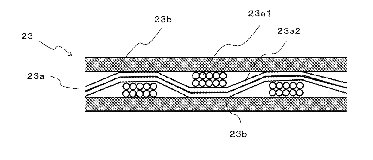
[0123]A 10-nm thick polyethylene film was superposed on the same glass cloth as used in Example 1, and heated at 180° C. for 20 minutes. This treatment allowed the glass cloth to be impregnated with the molten polyethylene. Next, on the surface of the glass cloth, cut glass wool was scattered in the same manner as in Example 1. The glass cloth on which cut glass wool was scattered was heated at 180° C. for 10 minutes, and consequently the polyethylene melted again allowed the glass wool to be fixed to the glass cloth. The glass cloth was cooled to room temperature, and then the glass wool not fixed to the glass cloth was removed. The thickness of the thus prepared separator was 28 μm. Accordingly, the thickness of the glass fiber layer was 8 μm. Otherwise under the same conditions as in Example 1, a secondary battery was prepared, and the prepared secondary battery was subjected to the same evaluations as in Example 1.


PUM

PropertyMeasurementUnit
thicknessaaaaaaaaaa
thicknessaaaaaaaaaa
melting pointaaaaaaaaaa

Abstract

The present invention provides a separator drastically reducing the short-circuit between electrodes and having satisfactory ionic conductivity on the basis of the use of inorganic materials. The separator 23 has a substrate 23a including a layer formed by using an inorganic material so as to have a plurality of openings, and an inorganic fiber layer 23b laminated on one surface or both surfaces of the substrate 23a so as to cover the openings of the substrate 23a without blocking the openings of the substrate 23a. The thickness of the separator 23 is 100 μm or less.

Description

CROSS-REFERENCE TO RELATED APPLICATIONS[0001]This application is a national stage application of International Application No. PCT / JP2013 / 080596 entitled “Separator, Electrode Element, Electric Energy Storage Device, and Method for Producing Separator,” filed on Nov. 12, 2013, which claims the benefit of the priority of Japanese Patent Application No. 2012-271288, filed on Dec. 12, 2012, the disclosures of each of which are hereby incorporated by reference in their entirety.TECHNICAL FIELD[0002]The present invention relates to a separator having a substrate containing an inorganic material, and an electrode element and an electric energy storage device using the separator. The present invention also relates to a method for producing the separator.BACKGROUND ART[0003]With the rapid expansion of the markets for notebook personal computers, cellular phones, electric vehicles and the like, electric energy storage devices such as capacitors and secondary batteries are actively investigat...

Claims


Application Information

Patent Timeline
Patent Type & Authority Patents(United States)
IPC IPC(8): H01M2/16H01G11/52H01M10/0525H01M2/14H01M10/052H01M50/406H01M50/434H01M50/449H01M50/497
CPCH01M2/145H01G11/52H01M2/1613H01M2/1673H01M2/1686H01M10/0525H01M10/052Y02E60/13Y10T156/10H01M50/44H01M50/449H01M50/497H01M50/434H01M50/406Y02T10/70Y02E60/10H01M50/46
Inventor SHIMURA, KENICHIINOUE, KAZUHIKO
Owner NEC CORP
Why Eureka
Try Eureka