
Automatic calibration sample selection for die-to-database photomask inspection

a technology of automatic calibration and die-to-database, which is applied in the direction of instruments, processor architecture/configuration, image analysis, etc., can solve the problems of large image field size of the photomask, the inability to inspect single die reticles with this method, and the complicated process of die-to-database inspection, etc., to improve the completeness and effectiveness of calibration sample selection, improve the robustness of the product, and reduce the requirement on the operator's knowledg

Active Publication Date: 2017-08-29
KLA CORP
View PDF8 Cites 3 Cited by
  • Summary
  • Abstract
  • Description
  • Claims
  • Application Information

AI Technical Summary

Benefits of technology

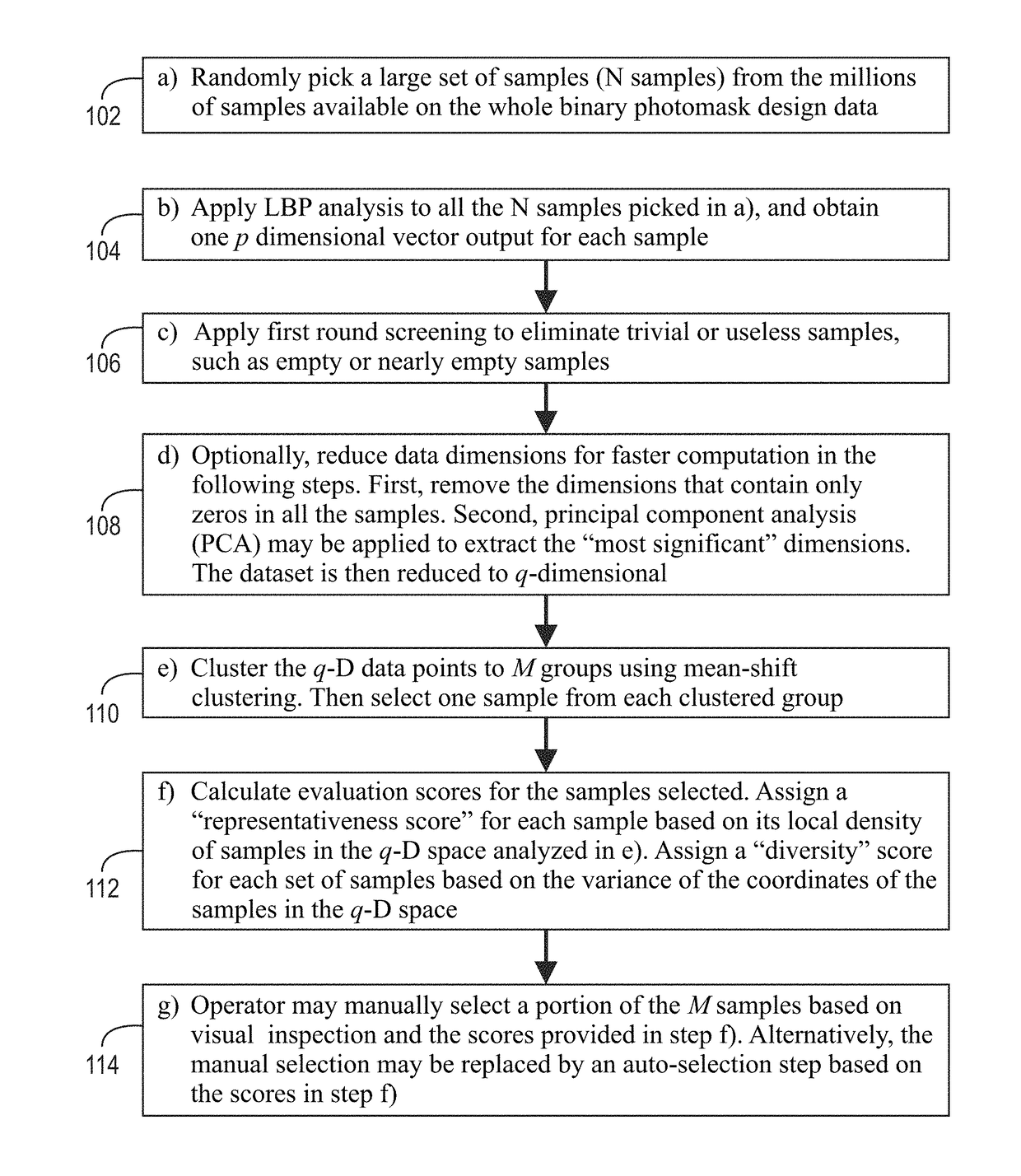
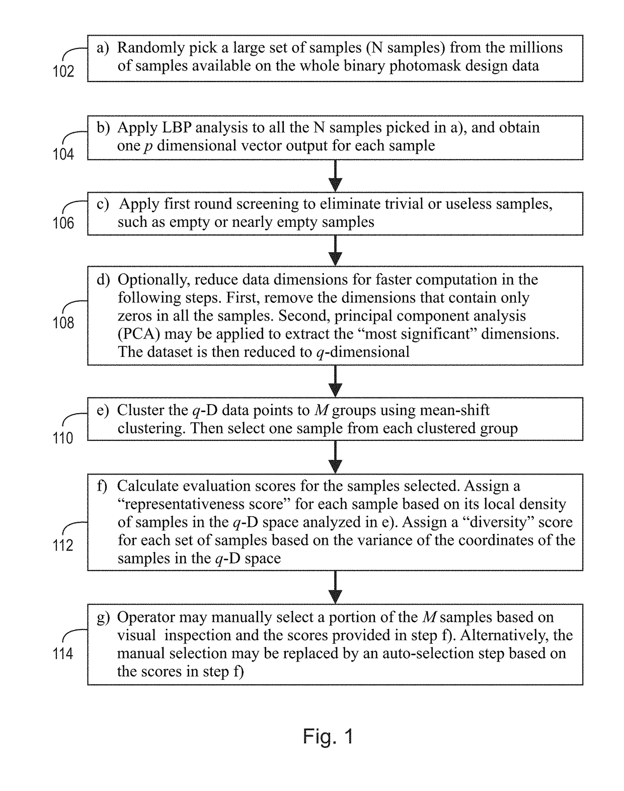
[0016]The present invention automates the selection process procedure and minimizes requirements on the operator's knowledge, significantly improving completeness and effectiveness of calibration sample selection. This enables standardized evaluation scores to replace subjective and unstable manual work, which improves robustness of the products. The method of the present invention is unlikely to increase inspection time, and, as a result, the inspection first-time success rate can be significantly improved.

Problems solved by technology

The step and repeat systems result in larger image field sizes on the photomask.
Since two or more dice with an identical design are needed for die-to-die inspection to work, single die reticles are not capable of being inspected with this method.
By its own nature, die-to-database inspection is a more complicated process, requiring advanced algorithms for both data rendering, image processing and defect detection.
It also requires more processing power.
As repeating the inspection procedure may take several hours, first-time failure can severely affect throughputs of customers' products.
One of the main causes for failure in die-to-database inspection is sub-optimal calibration results.
Generally, due to the enormous data, visual inspection of every sample is impractical, and hence the operator typically selects the calibration samples by: a) randomly picking a small set of samples, e.g., tens of samples, from the whole plate of a photomask; and, b) selecting an even smaller set of samples, usually less than 15, from the samples picked in step a) based on various factors.
Despite the knowledge of the operator, calibration samples are usually selected in a subjective and empirical way because there is no scientific evaluation of the process.
This can unpredictably cause calibration failure leading to inspection failure.
Further, the selection is likely to be incomplete.
The operator randomly picks tens of samples from millions of candidates, making it likely for the operator to miss important samples that have large impacts on the calibration.
For inexperienced operators or unfamiliar types of photomasks, selecting calibration samples can be time-consuming and challenging.

Method used


Image

  • Automatic calibration sample selection for die-to-database photomask inspection
  • Automatic calibration sample selection for die-to-database photomask inspection
  • Automatic calibration sample selection for die-to-database photomask inspection

Examples


Embodiment Construction

[0029]At the outset, it should be appreciated that like reference characters on different drawing views identify identical, or functionally similar, structural elements of the invention. While the present invention is described with respect to what is presently considered to be the preferred aspects, it is to be understood that the invention as claimed is not limited to the disclosed aspect. The present invention is intended to include various modifications and equivalent arrangements within the spirit and scope of the appended claims.

[0030]Furthermore, it is understood that this invention is not limited to the particular methodology, materials and modifications described and as such may, of course, vary. It is also understood that the terminology used herein is for the purpose of describing particular aspects only, and is not intended to limit the scope of the present invention, which is limited only by the appended claims.

[0031]Unless defined otherwise, all technical and scientifi...


PUM


Abstract

A method for selecting samples of reticle design data patterns in order to calibrate the parameters based on which the reference image used in a die-to-database reticle inspection method is rendered, the method comprising the steps of applying local binary pattern (LBP) analysis to a plurality of samples to obtain a p-dimensional vector output for each of the plurality of samples, clustering the q-D data points to M groups, selecting one sample from each clustered group, calculating evaluation scores for the samples selected, and, selecting a portion of the M samples on the representativeness score and the diversity score.

Description

CROSS-REFERENCE TO RELATED APPLICATIONS[0001]This application claims the benefit of U.S. Provisional Patent Application No. 61 / 988,908, filed on May 6, 2014, which application is incorporated herein by reference in its entirety.TECHNICAL FIELD[0002]The present invention relates generally to photomask inspection, and, more specifically, to die-to-database photomask inspection and, even more specifically, to automatic calibration sample selection for die-to-database photomask inspection.BACKGROUND[0003]A photomask, in general, is used in the intermediate step between the design of an integrated circuit and the actual wafer itself. The photomask acts as a stencil to print an image on the semiconductor material. In the past, the convention was a 1:1 transfer of the image from the mask to the wafer. The 1:1 transfer has given way to a “step and repeat” system utilizing reduction lens systems that expose a mask image stepped many times across the wafer plane. The step and repeat systems r...

Claims


Application Information

Patent Timeline
Patent Type & Authority Patents(United States)
IPC IPC(8): G06K9/00G06T7/00G06K9/52G06K9/62G06K9/46G06T1/20
CPCG06K9/52G06K9/6221G06T1/20G06T7/001G06K2009/4666G06T2207/30148G06V10/467G06F18/2321
Inventor ZHAO, FENGPAN, GANG
Owner KLA CORP
Learn More