
Tunable laser array system

a laser array and laser technology, applied in semiconductor lasers, instruments, applications, etc., can solve the problems of limited wavelength sweep range, limited imaging rate and sweep trajectories,

Active Publication Date: 2017-07-04
PRAEVIUM RES +1
View PDF20 Cites 14 Cited by
  • Summary
  • Abstract
  • Description
  • Claims
  • Application Information

AI Technical Summary

Benefits of technology

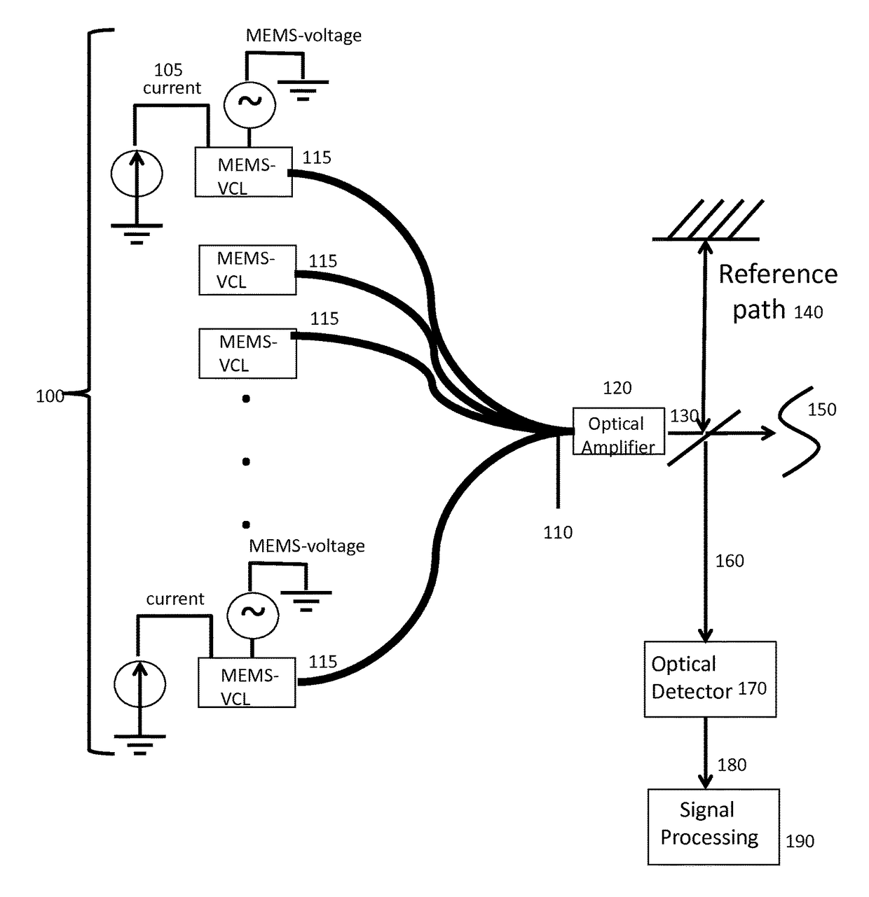
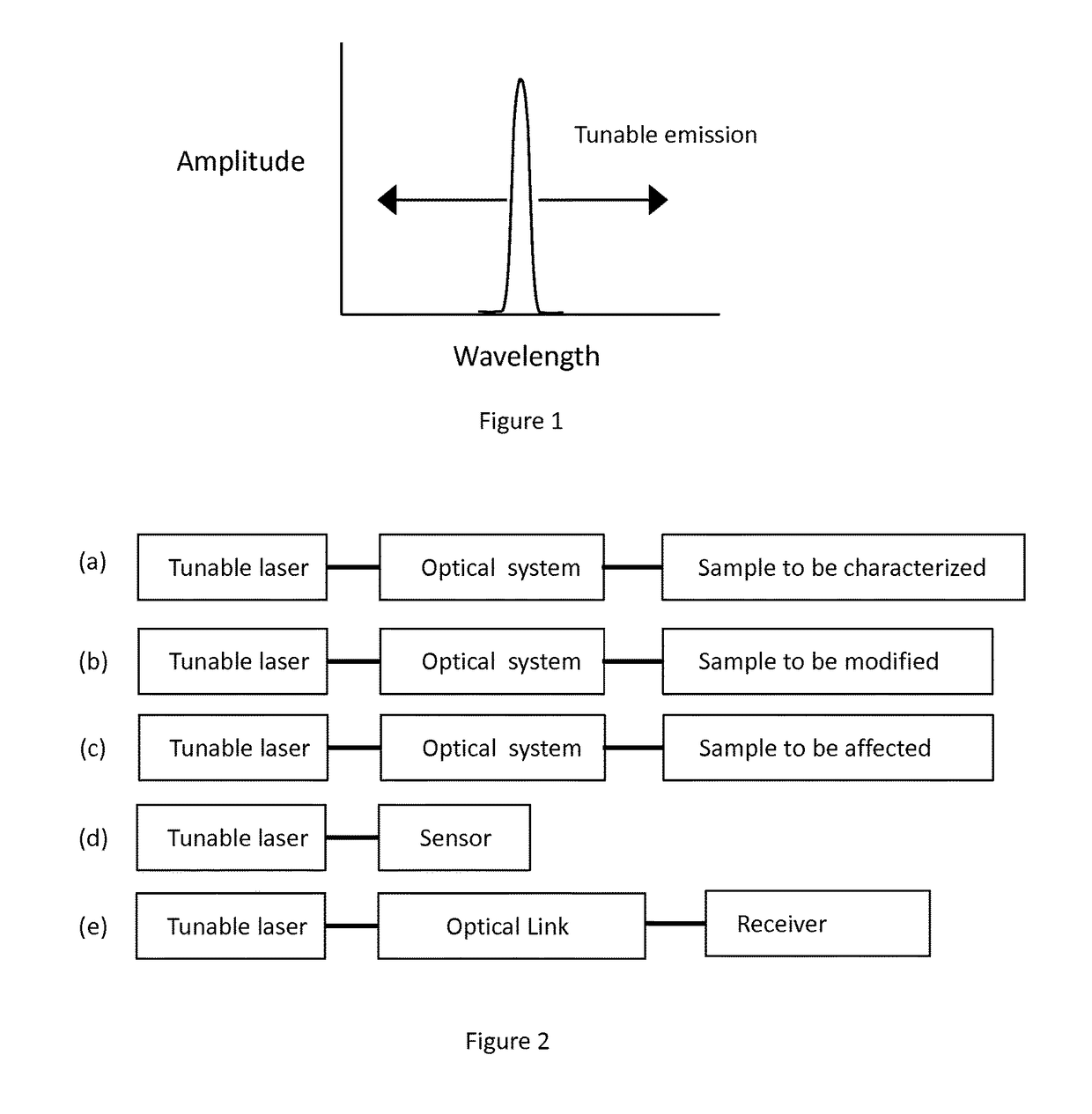
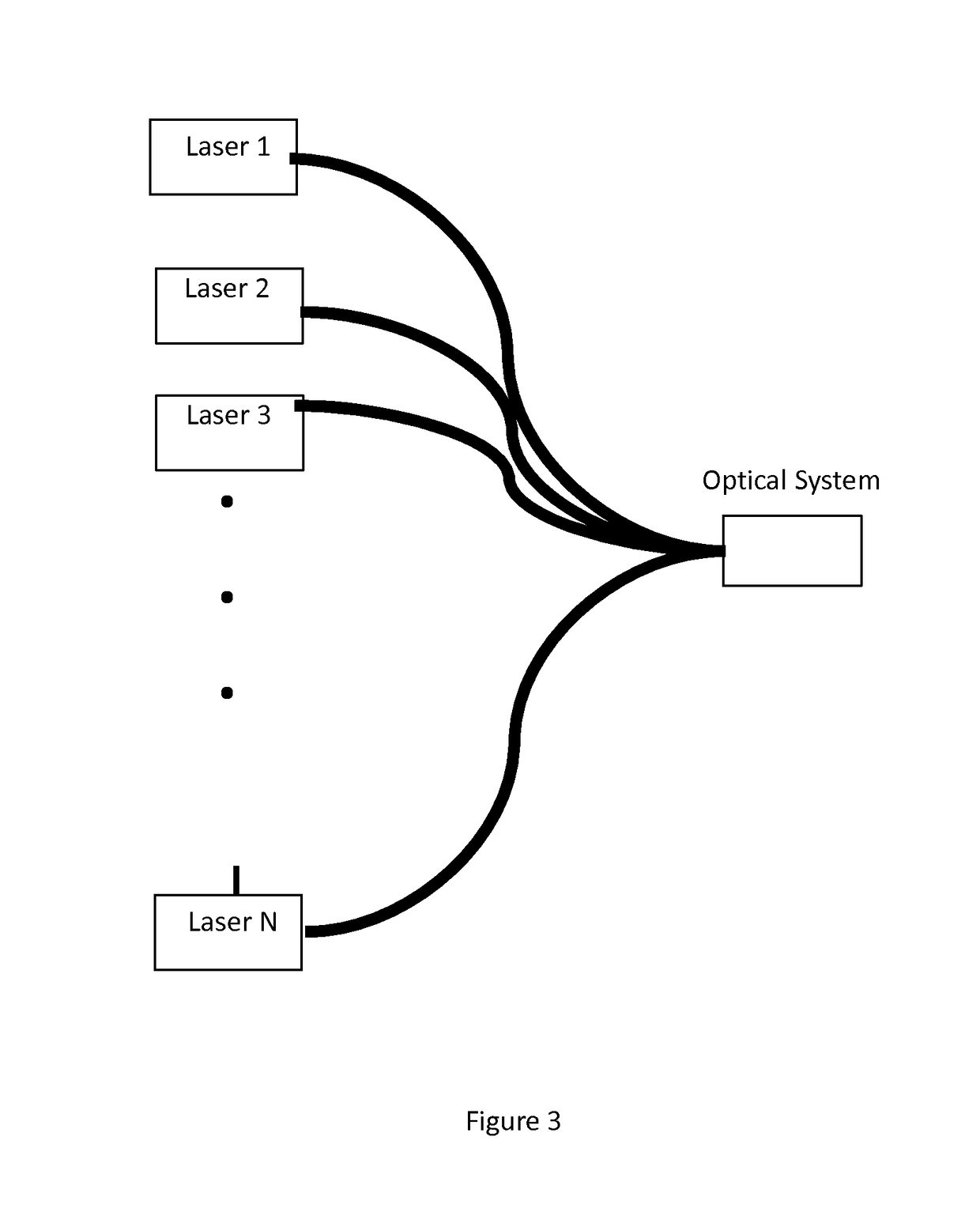
The present invention relates to a wavelength tunable laser that can be used in various applications such as spectroscopy, atomic or molecular excitation, optical coherence tomography imaging, and deformation or ablation of samples. The laser can be designed with a tunable filter element or by using an external wavelength tuning element such as a tunable optical filter or an external temperature control. The laser can be multiplexed into an optical system with other tunable lasers or external factors such as temperature or drive current. The invention also includes an array of tunable vertical cavity lasers (VCLs) that can be multiplexed together to achieve wider effective sweep range and higher sensitivity. The VCLs can be controlled by shaping the tuning curve or the wavelength range, sweep speed, and repetition rates. The invention also allows for flexibility in controlling the output power and wavelength tuning trajectory of the laser system. An optical amplifier can be used to increase the output power and control the output power as a function of time. The invention also includes the use of electro-optic modulators to control various properties of the laser output. Overall, the invention provides a multi-laser system with extended performance beyond the individual lasers.

Problems solved by technology

Nevertheless the imaging rates and sweep trajectories remain limited by the mechanical resonance and dynamic properties of a single MEMS actuator, and wavelength sweep range remains limited by the gain-bandwidth of a single semiconductor gain medium.

Method used


Image

  • Tunable laser array system
  • Tunable laser array system
  • Tunable laser array system

Examples


Embodiment Construction

[0036]The description of illustrative embodiments according to principles of the present invention is intended to be read in connection with the accompanying drawings, which are to be considered part of the entire written description. In the description of embodiments of the invention disclosed herein, any reference to direction or orientation is merely intended for convenience of description and is not intended in any way to limit the scope of the present invention. Relative terms such as “lower,”“upper,”“horizontal,”“vertical,”“above,”“below,”“up,”“down,”“top” and “bottom” as well as derivative thereof (e.g., “horizontally,”“downwardly,”“upwardly,” etc.) should be construed to refer to the orientation as then described or as shown in the drawing under discussion. These relative terms are for convenience of description only and do not require that the apparatus be constructed or operated in a particular orientation unless explicitly indicated as such. Terms such as “attached,”“affi...


PUM


Abstract

A system for swept source optical coherence tomography, the system including a light source emitting multiplexed wavelength-swept radiation over a total wavelength range, the light source including N wavelength-swept vertical cavity lasers (VCL) emitting N tunable VCL outputs having N wavelength trajectories, a combiner for combining the N tunable VCL optical outputs into a common optical path to create the multiplexed wavelength-swept radiation, a splitter for splitting the multiplexed wavelength-swept radiation to a sample and a reference path, an optical detector for detecting an interference signal created by an optical interference between a reflection from the sample and light traversing the reference path, and a signal processing system which uses the interference signal to construct an image of the sample, wherein at least one of the N wavelength trajectories differs from another of the N wavelength trajectories with respect to at least one parameter.

Description

CROSS REFERENCES TO RELATED APPLICATIONS[0001]This application claims the benefit of U.S. Provisional Patent Application No. 61 / 793,604 filed on Mar. 15, 2013. The disclosure of U.S. Provisional Patent Application 61 / 793,604 is hereby incorporated by reference.FIELD OF THE INVENTION[0002]This invention relates generally to tunable lasers and tunable laser applications, material or sample characterization, material or sample modification, optical coherence tomography, spectroscopy, sensors, measurement, communications, and vertical cavity lasers.BACKGROUND[0003]Wavelength tunable lasers and widely tunable lasers are integral components of a range of instruments, devices, and tools use for characterizing or modifying materials, objects, or samples. Wavelength tunable lasers and widely tunable lasers are also used in sensors and for data transmission and communication. In many applications, the wavelength is tuned continuously (e.g. the wavelength is swept in time) and possibly accordi...

Claims


Application Information

Patent Timeline
Patent Type & Authority Patents(United States)
IPC IPC(8): A61B3/14H01S5/183G01B9/02A61B3/10A61B3/00H01S5/30H01S5/40H01S5/06H01S5/20H01S5/42
CPCG01B9/02004A61B3/0008A61B3/102G01B9/02007G01B9/02091H01S5/18366H01S5/4087H01S5/0607H01S5/18308H01S5/18311H01S5/18341H01S5/18369H01S5/18372H01S5/18377H01S5/2059H01S5/3095H01S5/4012H01S5/423
Inventor JAYARAMAN, VIJAYSEKHARBURGNER, CHRISTOPHERJOHN, DEMISPOTSAID, BENJAMIN MICHAELCABLE, ALEX EZRA
Owner PRAEVIUM RES
Learn More