Hydraulic drive system
a technology of hydraulic drive and drive shaft, which is applied in the direction of servomotors, servomotor components, constructions, etc., can solve the problem of large hydraulic pump capacity, and achieve the effect of increasing the speed of the lowering of the work implemen
- Summary
- Abstract
- Description
- Claims
- Application Information
AI Technical Summary
Benefits of technology
Problems solved by technology
Method used
Image
Examples
first exemplary embodiment
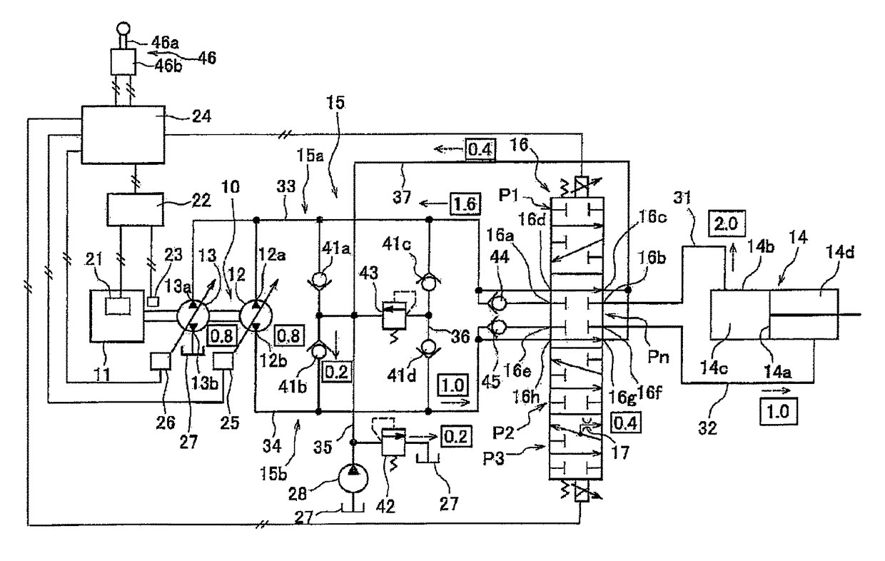
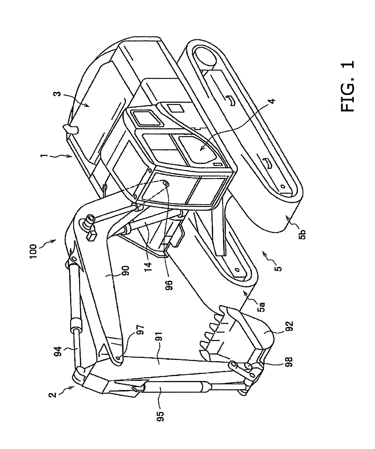
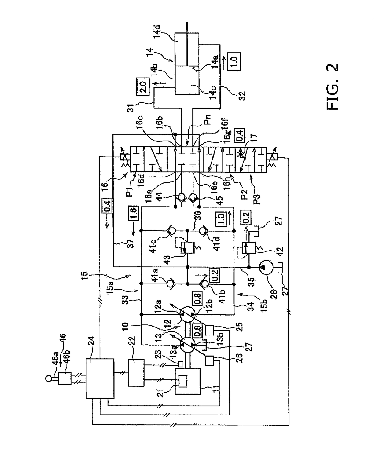
[0049]FIG. 1 is a perspective view of a hydraulic excavator 100 on which the hydraulic drive system according to a first exemplary embodiment of the present invention is mounted. The hydraulic excavator 100 is equipped with a vehicle body 1 and a work implement 2. The vehicle body 1 has an upper revolving unit 3, a cab 4, and an undercarriage 5. The upper revolving unit is disposed on the undercarriage 5. The upper revolving unit 3 is provided in a rotatable manner with respect to the undercarriage 5. The upper revolving unit 3 contains devices such as an engine and a hydraulic pump described below. The cab 4 is disposed in the front section of the upper revolving unit 3. An operating device described below is provided inside the cab 4. The undercarriage 5 includes crawler tracks 5a and 5b, and the hydraulic excavator 100 travels due to the rotation of the crawler tracks 5a and 5b.
[0050]The work implement 2 is attached to the front section of the vehicle body 1 and includes a boom ...
second exemplary embodiment
[0109]A hydraulic drive system according to a second exemplary embodiment of the present invention is illustrated in FIG. 5. The control valve 16 in the hydraulic drive system according to the second exemplary embodiment has a return flowpath 18 that allows communication between the first cylinder port 16b and the second cylinder port 16f in the third position state P3. When the control valve 16 is in the third position state P3, the return flowpath 18 branches off from the first flowpath 15a and returns a portion of the hydraulic fluid discharged from the first chamber 14c to the second flowpath 15b. A check valve 19 and a throttle 20 are disposed in the return flowpath 18. The check valve 19 allows the flow of hydraulic fluid from the first flowpath 15a to the second flowpath 15b. The check valve 19 prohibits the flow of hydraulic fluid from the second flowpath 15b to the first flowpath 15a.
[0110]The control valve 16 allows communication between the first bleed-off port 16c and t...
third exemplary embodiment
[0114]A hydraulic drive system according to a third exemplary embodiment of the present invention is illustrated in FIG. 6. The hydraulic drive system according to the third exemplary embodiment includes a bleed-off flowpath 38. The control valve 16 has a third bleed-off port 16i. The bleed-off flowpath 38 is connected to the third bleed-off port 16i and to the hydraulic fluid tank 27. The control valve 16 has the return flowpath 18 that allows communication between the first cylinder port 16b and the second cylinder port 16f in the third position state P3. When the control valve 16 is in the third position state P3, the return flowpath 18 is branched off from the first flowpath 15a and returns a portion of the hydraulic fluid discharged from the first chamber 14c to the second flowpath 15b. The check valve 19 and the throttle 20 are disposed in the return flowpath 18.
[0115]The control valve 16 allows communication between the first cylinder port 16b and the third bleed-off port 16i...
PUM
 Abstract
Description
Claims
Application Information
 - R&D
- Intellectual Property
- Life Sciences
- Materials
- Tech Scout
- Unparalleled Data Quality
- Higher Quality Content
- 60% Fewer Hallucinations
Browse by: Latest US Patents, China's latest patents, Technical Efficacy Thesaurus, Application Domain, Technology Topic, Popular Technical Reports.
© 2025 PatSnap. All rights reserved.Legal|Privacy policy|Modern Slavery Act Transparency Statement|Sitemap|About US| Contact US: help@patsnap.com


