Wheelchair
a technology for wheelchairs and wheelchairs, applied in wheelchairs/patient conveyances, medical transportation, ambulance services, etc., can solve the problems of inconvenient user standing alone, and achieve the effect of preventing unstableness
- Summary
- Abstract
- Description
- Claims
- Application Information
AI Technical Summary
Benefits of technology
Problems solved by technology
Method used
Image
Examples
first embodiment
[0035](First Embodiment)
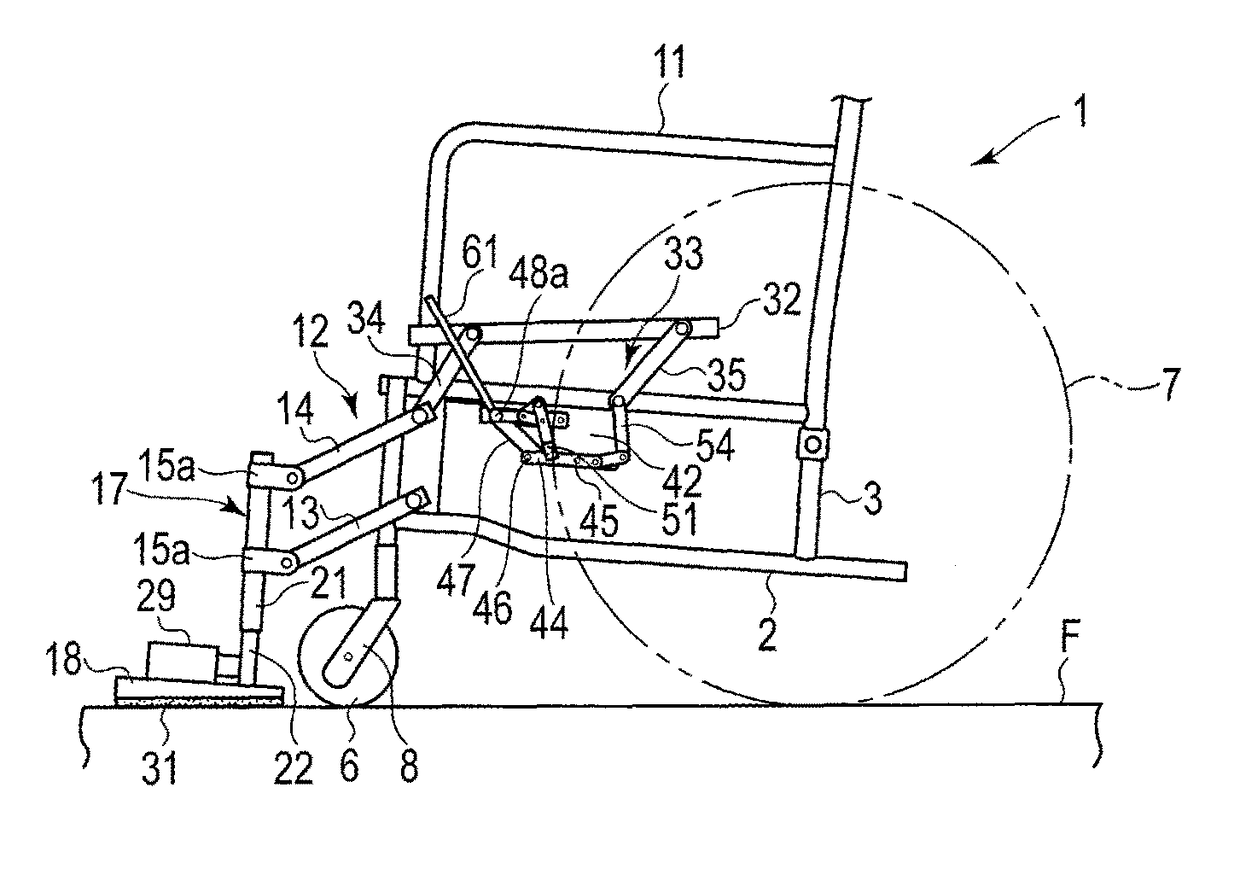
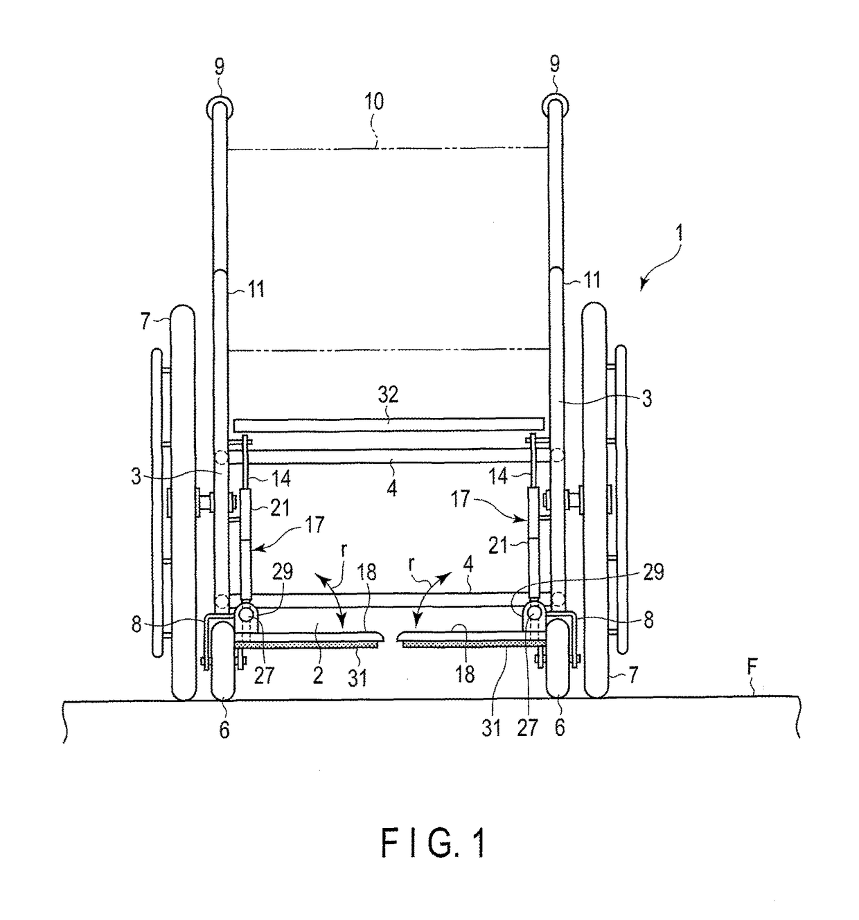
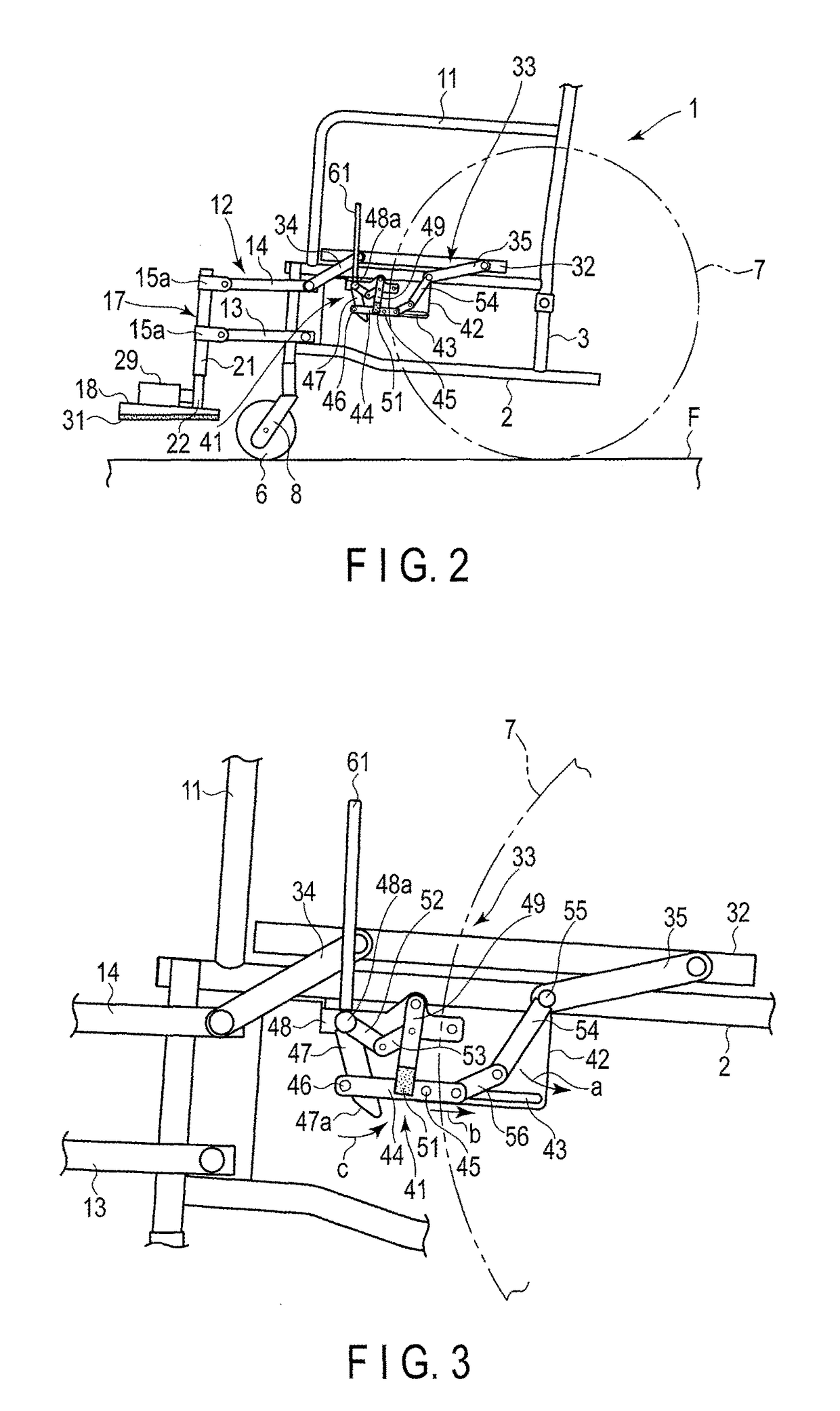
[0036]FIG. 1 to FIG. 9 show a first embodiment of the present invention. FIG. 1 is a front view of a wheelchair 1, and FIG. 2 is a side view thereof. The wheelchair 1 comprises a body 2 as a main body. The body 2 is structured by coupling a pair of side frames 3 formed in the shape of a rectangular frame in parallel to keep a predetermined distance therebetween by transverse pipes 4.
[0037]It should be noted that the body 2 may has the structure in which the pair of side frames 3 are coupled to be foldable in a width direction by links instead of the transverse pipes 4. That is, the body 2 may be foldable flat in the width direction.
[0038]Front wheels 6 are provided at the lower parts of pipes at the front ends of the pair of side frames 3, and rear wheels 7 are provided at intermediate parts of pipes at the back ends. The front wheels 6 and the rear wheels 7 contact a floor F, which is a contact patch.
[0039]To the lower ends of the pipes at the front ends of ...
second embodiment
[0116](Second Embodiment)
[0117]FIG. 10 and FIG. 11 show a wheelchair 1B according to a second embodiment of the present invention. The present embodiment is a modification of the second link mechanism 33 of the first embodiment. The same portions as those of the first embodiment are given the same symbols, and explanations thereof are omitted.
[0118]The second link mechanism 33 of the present embodiment is composed of one interlock link 63, one end of which is coupled and fixed to the bottom surface on the front end side of the seat 32 at a predetermined angle of inclination. The other end of the interlock link 63 is integrally attached to one end of the second link 14 of the first link mechanism 12, which is pivotally attached to the upper part on the front end side of the body 2. That is, the interlock link 63 rotates integrally with the second link 14.
[0119]In the present embodiment, the interlock link 63 is formed separately from the second link 14; however, they may be integrate...
third embodiment
[0136](Third Embodiment)
[0137]FIG. 12 to FIG. 14 show a third embodiment of the present invention. A wheelchair 1C of the third embodiment is a modification of the wheelchair 1 of the first embodiment. In the third embodiment, the same portions as those of the first embodiment are given the same symbols, and explanations thereof are omitted.
[0138]In the first embodiment, the footrests 18 are provided on the front end side of the body 2 to be movable up and down. However, in the third embodiment, footrests 18A are provided on the front end side of the body 2 to be not movable up and down, but are fixedly provided on the body 2.
[0139]To be specific, at the front ends of the pair of side frames 3 of the body 2, a pair of support members 71 (only one of which is shown in the figures) formed by bending pipe materials in a reverse L-shape is provided to project forward. In addition, the footrests 18A are attached to the lower ends of the support members 71.
[0140]On the top surfaces of the...
PUM
 Abstract
Description
Claims
Application Information
 - R&D
- Intellectual Property
- Life Sciences
- Materials
- Tech Scout
- Unparalleled Data Quality
- Higher Quality Content
- 60% Fewer Hallucinations
Browse by: Latest US Patents, China's latest patents, Technical Efficacy Thesaurus, Application Domain, Technology Topic, Popular Technical Reports.
© 2025 PatSnap. All rights reserved.Legal|Privacy policy|Modern Slavery Act Transparency Statement|Sitemap|About US| Contact US: help@patsnap.com


