
Viewing device, stereo projection system, and use of cyanine dyes in a supramolecular J-aggregate configuration

a viewing device and cyanine dye technology, applied in optics, instruments, electrical equipment, etc., can solve the problems of low efficiency, low efficiency, and difficulty in achieving the effect of reducing the cost of production and maintenance, and avoiding the loss of brightness

Active Publication Date: 2017-05-16
INFITEC
View PDF38 Cites 3 Cited by
  • Summary
  • Abstract
  • Description
  • Claims
  • Application Information

AI Technical Summary

Benefits of technology

The present invention aims to provide economical viewing devices for stereo projection systems with limited use. The invention has particularly strong advantages when using cyanine dyes in the supramolecular J-aggregate configuration as the absorbing substance. The use of filters containing only one cyanine dye is sufficient for creating a good stereo effect, as crosstalk between the viewer's two eyes in one of the pass bands can be reduced. The invention also allows for the use of other dyes, such as rhodamimes and squaraines. The plurality of individual filter layers in the system allows for individual design of each blocking region and ensures homogeneity over the entire area of the viewing window. This homogeneity contributes significantly to the quality of the stereo impression.

Problems solved by technology

In addition, temporal offsets and / or polarization differences can be provided; however, this leads to a loss of brightness, and is thus undesirable as a general rule.
In practice, it will seldom be possible to design the filter characteristics of the viewing windows such that zero transmission is actually present in the blocking region.
However, their manufacture is very complex and expensive.
Moreover, a stiff carrier is a mandatory requirement, which is disadvantageous with regard to weight and shape adjustment.
These disadvantages weigh especially heavily in the customary, eyeglass-like design of viewing devices for stereoscopic cinema projection systems, in which the stereoscopic eyeglasses must be made large enough that they can also be worn over ordinary corrective eyeglasses.
In addition, the filter spectrum of interference filters is heavily dependent on the angle of incidence of the light, and hence on the position of the viewer or the reflection location on the screen, both of which are disadvantageous in large movie theaters with a wide screen.
Another disadvantage for the purposes of stereoscopic cinema projection is the durability of the prior art interference filter glasses.
Because of the high costs of conventional interference glasses, this is only practical within the framework of rental.
But this entails additional difficulties with regard to theft prevention and hygiene.

Method used


Image

  • Viewing device, stereo projection system, and use of cyanine dyes in a supramolecular J-aggregate configuration
  • Viewing device, stereo projection system, and use of cyanine dyes in a supramolecular J-aggregate configuration
  • Viewing device, stereo projection system, and use of cyanine dyes in a supramolecular J-aggregate configuration

Examples


Embodiment Construction

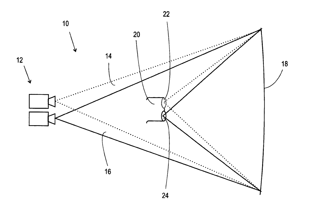
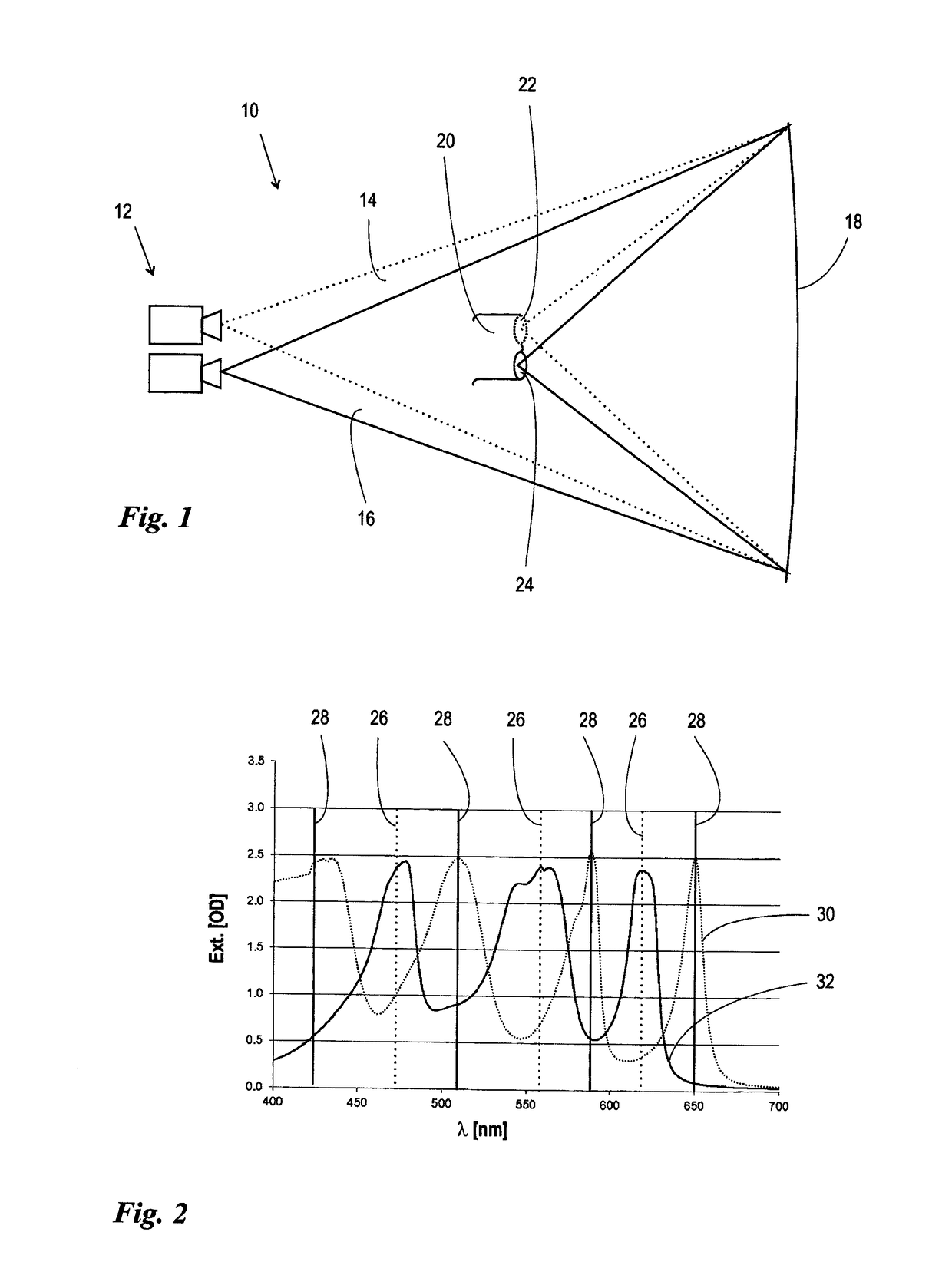
[0034]FIG. 1 shows a schematic representation of a stereo projection system 10. The system has a stereo projection unit 12, which is shown as two separate projectors in FIG. 1. Usually, special stereo projectors are used; a multiplicity of variants is known for these. Common to all of these variants is the result that two images 14, 16, which depict an object from different viewing angles, are projected congruently onto one another on a projection screen 18. The view angles 14, 16 typically correspond to the angles with which the image of an object is formed by the left or right eye of a viewer. Such images can be generated by shooting an object from different camera angles. Alternatively, they can also be computed by a digital data processing system and produced by means of a suitable projection unit 12. Accordingly, the projection unit 12 can involve analog transmitted-light projectors equally well as digital projectors that construct the images 14, 16 through superposition of dif...


PUM


Abstract

A viewing device for a stereo projection system, having a first and a second viewing window, each having an optically filtering filter layer system, wherein each viewing window has a filter spectrum in the visual spectral range having a plurality of pass bands that are separated from each other by blocking regions, and wherein each pass band of the filter spectrum of the first viewing window is covered by an associated blocking region of the filter spectrum of the second viewing window. Each filter layer system can be designed as an absorption filter layer system having a plurality of substances absorbing in differing spectral ranges, wherein at least one of the absorbing substances is a cyanine dye in the supramolecular configuration of a J-aggregate.

Description

[0001]This nonprovisional application is a continuation of International Application No. PCT / EP2012 / 005109, which was filed on Dec. 11, 2012, and which claims priority to German Patent Application No 10 2011 120 834.1, which was filed in Germany on Dec. 13, 2011, and which are both herein incorporated by reference.BACKGROUND OF THE INVENTION[0002]Field of the Invention[0003]The invention relates to a viewing device for a stereo projection system, having a first and a second viewing window, each having an optically filtering filter layer system, wherein each viewing window has a filter spectrum in the visual spectral range with a plurality of pass bands that are separated from each other by blocking regions, and wherein each pass band of the filter spectrum of the first viewing window is covered by an associated blocking region of the filter spectrum of the second viewing window.[0004]The invention also relates to a stereo projection system having a projection unit that projects a fi...

Claims


Application Information

Patent Timeline
Patent Type & Authority Patents(United States)
IPC IPC(8): G02B27/22G02B5/22H04N13/04H04N13/363
CPCG02B27/22G02B5/223G02B27/2207H04N13/0431H04N13/0459H04N13/363H04N13/334G02B30/23
Inventor BAUM, MAXIMILIAN
Owner INFITEC
Learn More