
Antenna for portable device

a portable device and antenna technology, applied in the direction of antennas, antenna details, antenna earthings, etc., can solve the problems of limiting space or region, difficult to achieve the mounting space of the connecting member, and serious degradation of flexibility in designing the antenna device, so as to achieve stable radiation performance

Active Publication Date: 2017-05-09
SAMSUNG ELECTRONICS CO LTD
View PDF6 Cites 0 Cited by
  • Summary
  • Abstract
  • Description
  • Claims
  • Application Information

AI Technical Summary

Benefits of technology

[0013]Accordingly, an aspect of the present invention is to provide an antenna device capable of providing a stable radiation performance when installed internally within a miniaturized and lightweight portable device.
[0014]Another aspect is to provide an antenna device capable of improving the flexibility of design inside a portable device by using a connecting member within the portable device, in particular, a connecting member case of a conductive material.
[0015]Further, still another aspect is to provide an antenna device capable of efficiently using an internal space of a portable device by using a connecting member case installed within the portable device as a ground connection path to the radiator.

Problems solved by technology

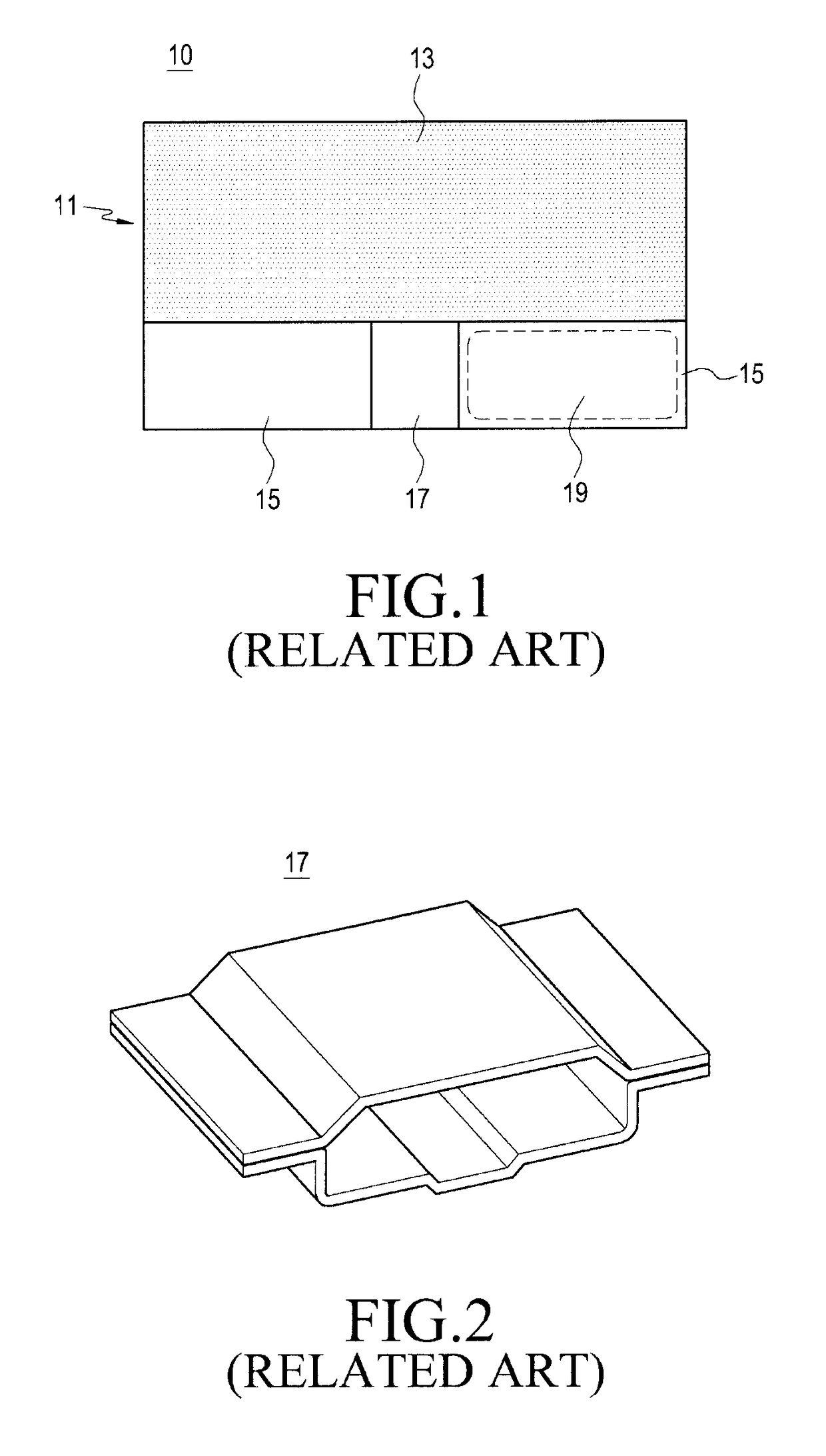
The smaller size makes it more difficult to achieve a requisite connecting member mounting space, a fill-cut region 15 for disposing an antenna device, and so on.
However, such an arrangement of the connecting member may limit a space or region 19 where an antenna device may be installed.
That is, the flexibility in designing an antenna device is seriously degraded.
Further, it is necessary to keep portable terminal thickness to a minimum in order to miniaturize and lighten the portable terminals as the sizes of displays increase, and the ability to provide a built-in antenna device capable of achieving a stable radiation performance has reached a limit.
In addition, when a plurality of antenna devices are installed in a single terminal in order to use various types of communication standards, for example, mobile communication, WLAN (Wireless Local Area Network), Bluetooth™, and NFC (Near Field Communication), arranging all the antenna devices inside the portable terminal is even more challenging.

Method used


Image

  • Antenna for portable device
  • Antenna for portable device
  • Antenna for portable device

Examples


Embodiment Construction

[0030]Hereinafter, various embodiments of the present invention will be described with reference to the accompanying drawings. In the following description, a detailed description of known functions and configurations incorporated herein will be omitted to avoid obscuring the subject matter of the present invention.

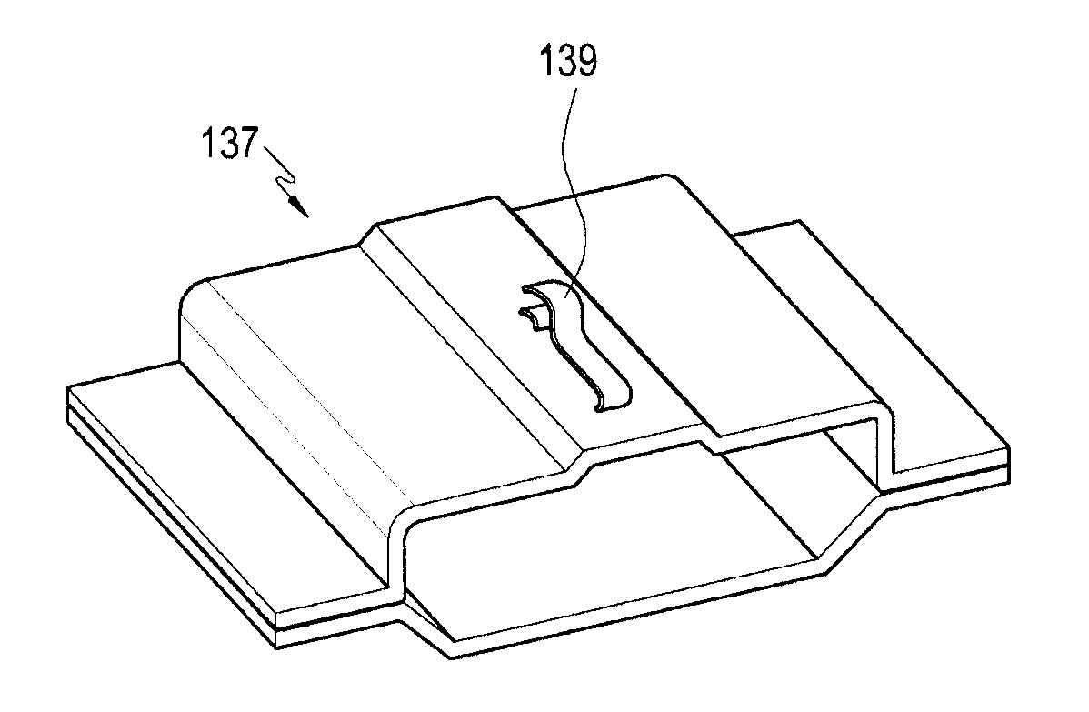
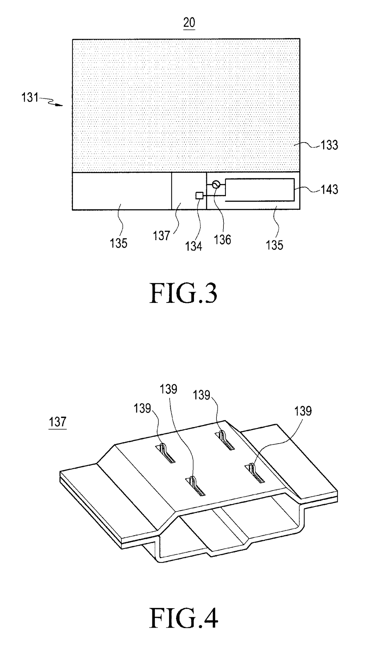
[0031]The inventive antenna device of a portable terminal (equivalently, “portable device”) is configured such that a radiator is spaced from a circuit board and connected to a ground surface of the circuit board through a connecting member such as a USB connector, more specifically, through a conductive case of the connecting member. A connecting pin, for example, a flexible member can be provided between the radiator and the case to ensure a stable connection between the case and the radiator.

[0032]According to an exemplary embodiment, the connecting pin may be mounted on the case or provided by processing a part of the case. Alternatively, the connecting pin may be mou...


PUM


Abstract

An antenna device of a portable device such as a smartphone includes a connecting member having a conductive case and mounted on a circuit board of the portable device in a manner such that the case is connected to a ground surface of the circuit board; a radiator spaced from the circuit board; and at least one connecting pin provided between the case and the radiator. The radiator is connected to the ground surface through the connecting pin and the case. The antenna device advantageously may be easily installed in the internal space of a miniaturized, lightened and / or slimmed portable device by practically using a conductive component, e.g., the case, of the connecting member.

Description

CLAIM OF PRIORITY[0001]This application claims priority under 35 U.S.C. §119 a Korean Application Serial No. 10-2013-0033475, which was filed in the Korean Intellectual Property Office on Mar. 28, 2013, the entire content of which is hereby incorporated by reference.BACKGROUND[0002]1. Technical Field[0003]The present disclosure relates generally to a portable electronic device, and particularly to a built-in antenna of a portable device.[0004]2. Description of the Related Art[0005]A portable terminal (portable device) is generally considered any hand held electronic device capable of receiving and / or transmitting an information or communication signal. Today's ubiquitous portable devices such as smartphones typically perform a variety of function such as voice communication, short message transmission, a multimedia function such as playing music or reproducing video, and an entertainment function such as a game. Such portable terminals may be classified into various types considerin...

Claims


Application Information

Patent Timeline
Patent Type & Authority Patents(United States)
IPC IPC(8): H01Q1/24H01Q1/38
CPCH01Q1/243H01Q1/38H01Q1/24H01Q1/48H04B1/40
Inventor PARK, HOONKIM, HO-SAENGKIM, YEON-WOOJEONG, SEONG-TAEHAN, SANG-MIN
Owner SAMSUNG ELECTRONICS CO LTD
Learn More