Eureka AIR delivers breakthrough ideas for toughest innovation challenges, trusted by R&D personnel around the world.

Flat panel speaker

a flat panel speaker and loudspeaker technology, applied in the field of loudspeakers, can solve the problems of substantial reduction of the likelihood of membrane tearing or having a distorted membrane surface, and achieve the effect of improving sound radiation capability and improving sound clarity

Inactive Publication Date: 2005-08-02
DIGITAL SONICS
View PDF27 Cites 37 Cited by
  • Summary
  • Abstract
  • Description
  • Claims
  • Application Information

AI Technical Summary

Benefits of technology

[0015]A compact, flat speaker of the present invention emits high quality sound over a wide bandwidth. Further, the manufacturing costs for the speaker are minimized by providing a speaker that is easy and inexpensive to manufacture. In addition, the speaker configuration substantially reduces the likelihood of membrane tearing or having a distorted membrane surface.
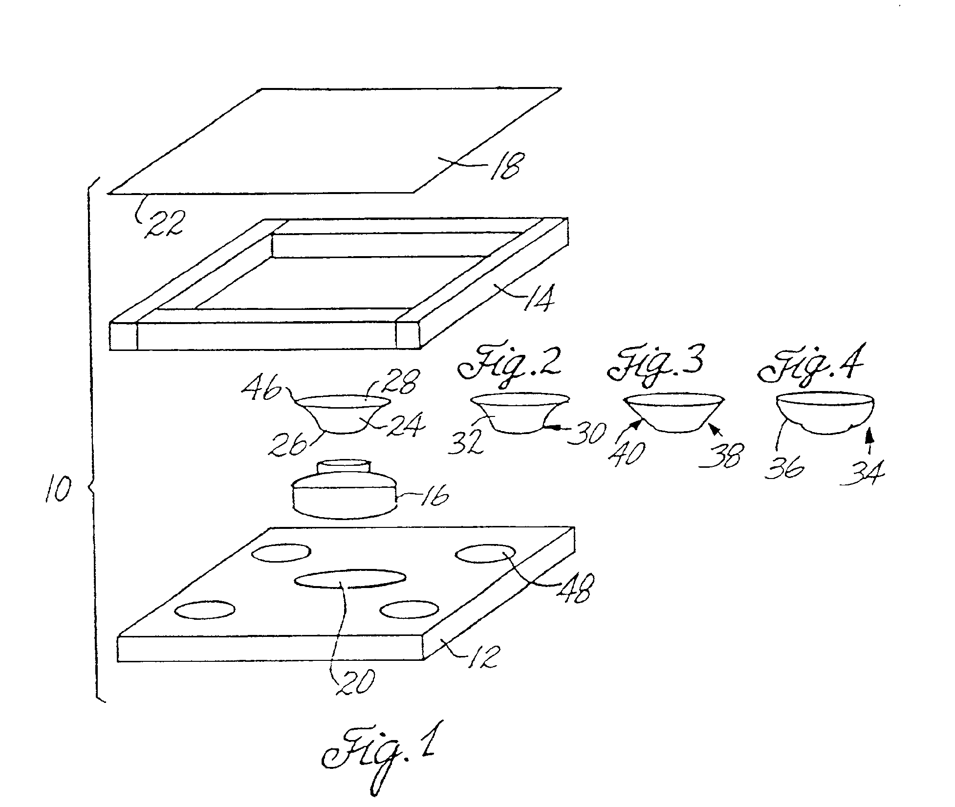
[0017]Clarity of sound can be further improved by including a plurality of sound breathers in the back plate of the speaker. For improved sound radiation capability, especially in the middle and high frequency sound ranges, the size and the shape of the enhancer can be modified in various ways, including a frustoconical, parabolic, or bell-shaped enhancer.

Problems solved by technology

In addition, the speaker configuration substantially reduces the likelihood of membrane tearing or having a distorted membrane surface.

Method used


Image

  • Flat panel speaker
  • Flat panel speaker
  • Flat panel speaker

Examples


first embodiment

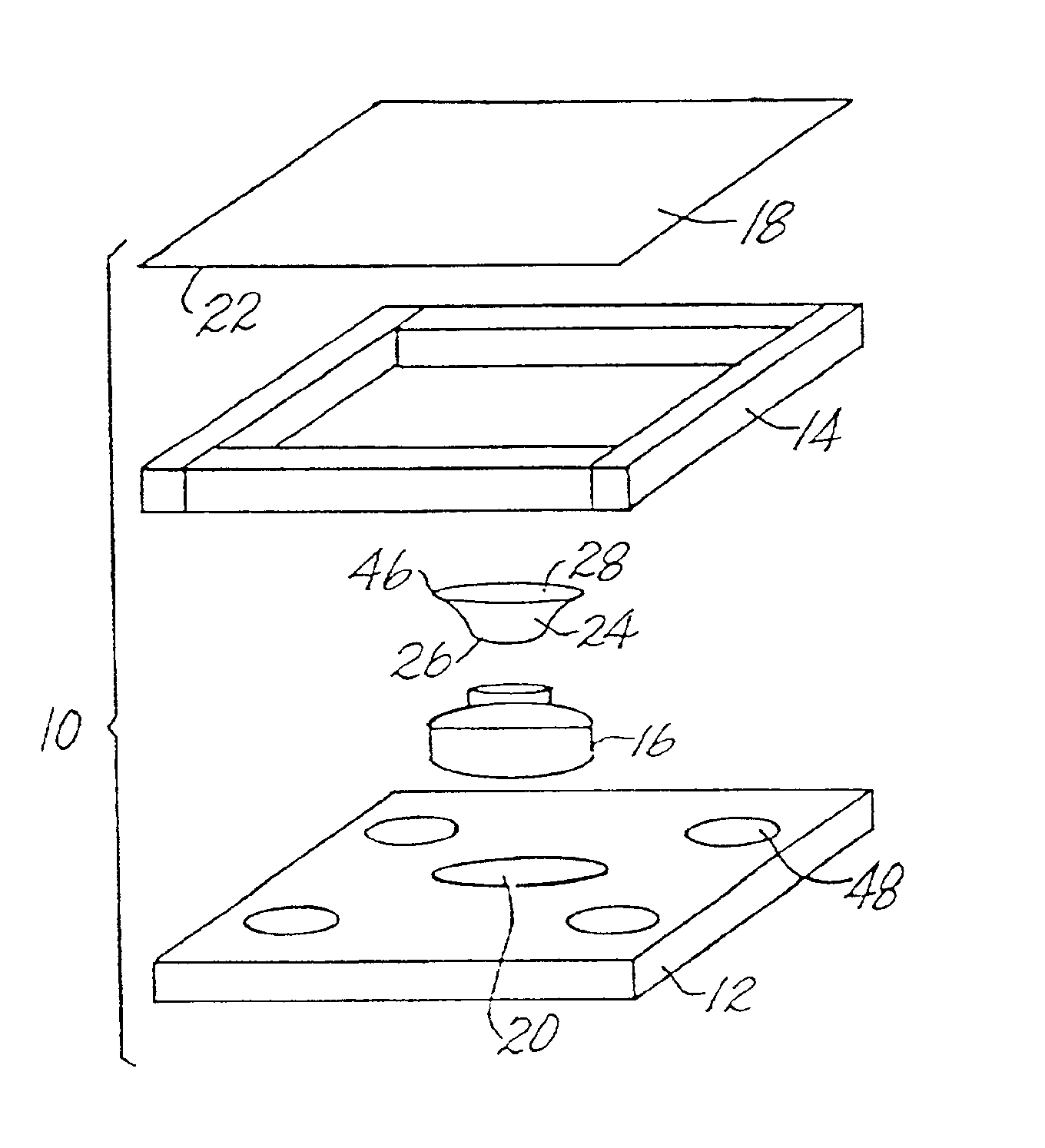
[0037]FIG. 1 illustrates an expanded view of a flat panel loudspeaker 10. The flat panel loudspeaker 10 has a back plate 12 with a driver 16, an open frame member 14 coupled with the back plate, a sound enhancer 24 coupled with the driver 16, and a membrane (or diaphragm) 18 attached to the sound enhancer and stretched across the frame member 14. The driver 16 vibrates in response to an electrical signal, which in turn vibrates the sound enhancer 24 and membrane 18, thereby producing sound.

[0038]The back plate 12 and frame member 14 provide structural support for the speaker 10 and can be made of any rigid material that will maintain the structural integrity of the speaker while in use. The materials for the back plate and frame member may include a hard plastic, a metal (i.e., Aluminum), and / or wood.

[0039]In one embodiment, the thickness of the back plate 12 together with the attached and / or integral frame member 14 is equal to the sum of the thicknesses of the driver 16 and the en...

second embodiment

[0070]One embodiment with a circular-shaped clamp means, or clamp ring, is shown in FIG. 13. FIG. 13 illustrates an expanded view of a flat panel loudspeaker 200. The flat panel loudspeaker 200 has a back plate 202 with the driver 16, an open frame member (or base) 210 coupled with the back plate, the sound enhancer 24 coupled with the driver 16, a membrane (or diaphragm) 216 attached to the sound enhancer and stretched across the base 210, a clamp ring 212 to press fit over the membrane and base, a cover 60 with a wire mesh 62 to protect the membrane, and cloth 64 over the wire mesh.

[0071]The flat panel loudspeaker 200 operates similarly to the flat panel loudspeaker 10; for example, the driver vibrates in response to an electrical signal, which in turn vibrates the sound enhancer and membrane, thereby producing sound. FIG. 14 illustrates a plan view of the speaker 200 with the back plate 202, the driver 16, the enhancer 24, and the base 210. FIG. 15 shows a cross-sectional view of...


PUM


Abstract

A loudspeaker having a back plate, a driver attached to the back plate, the driver being responsive to an electrical signal, an enhancer having a neck and a mouth, the neck attached to the driver and movable in accordance with the movement of the driver, a thin film membrane, the membrane attached to the enhancer, the membrane stretched over the frame, a frame for supporting the membrane and maintaining it in a taut state, and a rubber type adhesive for dampening the membrane resonances and for adhering the membrane to the frame. Clarity of sound can be further improved by including a plurality of sound breathers in the back plate of the speaker. For improved sound radiation capability, the size and the shape of the enhancer can be modified in various ways, including a frustoconical, parabolic, or bell-shaped enhancer.

Description

[0001]This is a Continuation-in-Part of International Application PCT / US00 / 40475, with an international filing date of Jul. 24, 2000, which claims the priority of U.S. Provisional Application No. 60 / 145,368 filed Jul. 23, 1999.BACKGROUND OF THE INVENTION[0002]1. Field of the Invention[0003]This invention relates to loudspeakers and more particularly to loudspeakers having a flat panel design.[0004]2. Description of the Related Art[0005]Dynamic loudspeakers typically include a relatively stiff diaphragm that is coupled to an electromagnetic driver assembly, which basically comprises a voice coil and a permanent magnet. Such loudspeakers are usually mounted so as to occupy an opening in an enclosure or baffle. The interaction of the magnetic field of the permanent magnet and the varying magnetic field of the voice coil that is produced when a changing current is passed through the voice coil causes the loudspeaker diaphragm to vibrate. Vibration of the diaphragm causes movement of air...

Claims


Application Information

Patent Timeline
Patent Type & Authority Patents(United States)
IPC IPC(8): H04R7/04H04R7/00H04R9/04H04R7/02H04R7/22H04R9/02
CPCH04R7/04
Inventor PETROFF, MICHAELYANAGAWA, MAYUKIMUTO, KEIKO
Owner DIGITAL SONICS
Why Eureka
Eureka Blog
Learn More