
Methods and apparatus for adjusting ice slab bridge thickness and initiate ice harvest following the freeze cycle

a technology of ice bridge and ice making cycle, which is applied in the direction of ice production, lighting and heating apparatus, domestic applications, etc., to achieve the effect of simple and quick adjustment, increase or decrease the ice making cycle time, and conserve water

Active Publication Date: 2017-04-18
PENTAIR FLOW SERVICES
View PDF36 Cites 9 Cited by
  • Summary
  • Abstract
  • Description
  • Claims
  • Application Information

AI Technical Summary

Benefits of technology

[0010]The second float clip is adjustable by the end user to any one of five (5) settings. The adjustable float clip adjusts the level of the second float which sets the maximum water level in the sump tank available and to be used for ice making. In this manner, the user can select the ice bridge thickness preferred for its own establishment, can conserve water, or can increase or decrease the ice making cycle time, all by the simple expedient of adjusting the second float clip (and, of course, the second float).
[0011]The use of the adjustable float clip allows for simple and quick adjustment of the float in the field by the end user and eliminates the need for special technician servicing or costly repair and down time. The use of the first float clip to set the minimum water level preferably to also signal for the initiation of harvesting allows for the elimination of an ice thickness probe to initiate the harvest cycle, and renders the manufacture and repair (if needed) more simple, without the need to disassemble the ice making machine. The use of the adjustable float clip to set the maximum water level also creates an adjustment method that is NSF compliant. In addition, the float clips and floats can be removed for cleaning without the use of tools, because in a preferred embodiment of the present disclosure, the ice float clips snap easily into and out of place and, in any event, the floats themselves can be slipped out of the clips to be cleaned or replaced. Slime buildup on the float sensors themselves is also reduced.
[0012]An additional benefit of the present disclosure includes that there is provided a batch water system which allows for more even ice fill patterns. Using an ice thickness probe (which can only measure the thickness of the ice bridge at one location) to initiate the harvest cycle of the ice making machine can result in variation in each batch of ice made (due, e.g., to the fact of potential ice buildup on the ice thickness probe itself). According to the present disclosure, by using the float clips to adjust the floats, the water usage is more consistent due to the fact that it is the quantity of water set by the end user which determines the ice bridge thickness. Only when all of the available water in the sump tank is used, and the water level drops to the level of the first float does the ice harvest cycle begin. Thus, the same amount of water is used for each cycle.
[0013]A corollary to the foregoing benefit is that the batch water system of the present disclosure reduces the energy consumption and water use. In the prior art ice making machines, excess water had to be contained in the sump tank to insure that the ice bridge thickness was reached before harvest. This excess water was then pumped out of the sump tank upon initiation of the ice harvest cycle. According to the present disclosure, only a minimum amount of water remains in the sump tank at the time of harvest, and all of the water above this level is used to make ice. This allows for the control of the amount of water which can be critical in many situations.

Problems solved by technology

The water level allowed by one float in a float clip is set upon manufacture and cannot be adjusted by the user.

Method used


Image

  • Methods and apparatus for adjusting ice slab bridge thickness and initiate ice harvest following the freeze cycle
  • Methods and apparatus for adjusting ice slab bridge thickness and initiate ice harvest following the freeze cycle
  • Methods and apparatus for adjusting ice slab bridge thickness and initiate ice harvest following the freeze cycle

Examples


Embodiment Construction

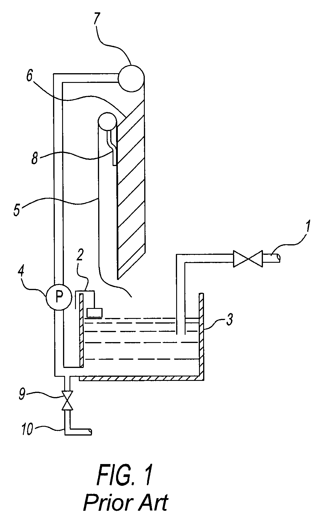
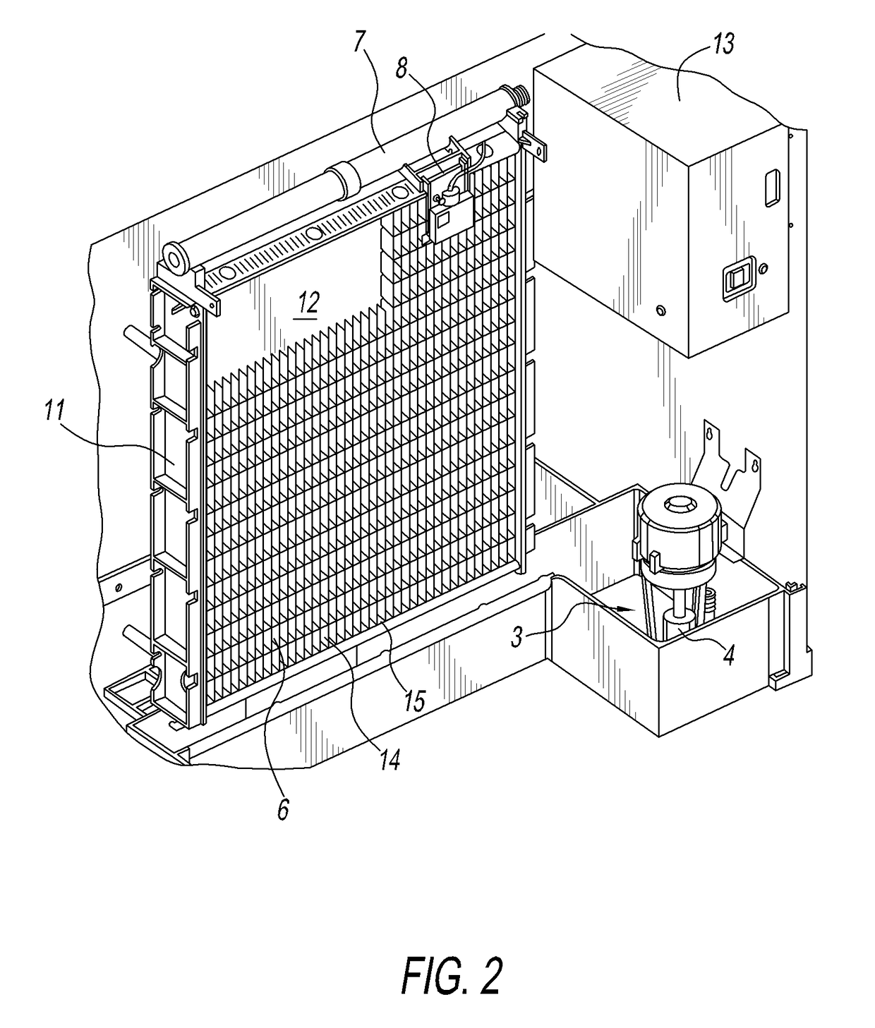
[0026]The general configuration of an ice making machine of the present disclosure will be described in connection with FIGS. 1 and 2 which depict a prior art ice making machine. This description will show how the present disclosure differs from and improves upon the prior art.

[0027]As shown in FIG. 1, the typical water system for cube ice machines includes a water supply or inlet 1. A water level probe 2 is used to control the depth of water in a sump tank 3. A circulating pump 4 draws water out of the sump and pumps it up to a distributor tube 7. Water falls from the distributor tube 7 over the ice-forming mold, sometimes also known as an evaporator plate 6. Water curtain 5 keeps water from splashing out of the front of the water compartment and directs water that does not freeze back into the sump tank 3. An ice thickness sensor or probe 8 is used to monitor the build-up of the ice bridge on the front of the ice-forming mold 6. The ice thickness sensor initiates the ice harvest c...


PUM


Abstract

A method and apparatus for adjusting and controlling ice bridge slab thickness and / or initiation of ice harvest following a freeze cycle. This adjusting and controlling is performed through the use of adjustable float clip assemblies which set the amount of water available for ice making in a batch process. The adjustable float clip assemblies provide an ice machine user with the ability to easily adjust the ice slab bridge thickness to a single or plurality of settings, and allow for changes in ice bridge slab thickness at the site of installation.

Description

CROSS-REFERENCED APPLICATION[0001]This application claims priority to U.S. Provisional Application No. 61 / 670,291, filed on Jul. 11, 2012, which is incorporated herein in its entirety by reference thereto.BACKGROUND OF THE DISCLOSURE[0002]1. Field of the Disclosure[0003]The present disclosure relates to methods and apparatus for adjusting and controlling ice bridge slab thickness and initiation of ice harvest following the freeze cycle. The adjusting and controlling are performed through the use of adjustable float clip assemblies which set the amount of water available for ice making in a batch process. As such, the adjustable float clip assemblies provide an ice machine user with the ability to easily adjust the ice slab bridge thickness to one of up to five settings. The three primary settings use the general nomenclature of “low”, “medium” and “high”, while the remaining two settings use the nomenclature “very low” and “very high”. The methods and apparatus of the present disclo...

Claims


Application Information

Patent Timeline
Patent Type & Authority Patents(United States)
IPC IPC(8): F25C1/00F25C1/12F25C1/22
CPCF25C1/00F25C1/12F25C1/22F25C2400/14F25C2700/04
Inventor ANTOINE, THOMAS H.CAYEMBERG, CURT R.PETERSEN, DEAN M.GIEBEL, MARK P.
Owner PENTAIR FLOW SERVICES
Learn More