
Flush valve handle assembly providing dual mode operation

a technology of handle assembly and flush valve, which is applied in the direction of valve operating means/releasing devices, engine components, mechanical equipment, etc., can solve the problem that the non-symmetrical portion of the handle assembly is not visible to the installer

Active Publication Date: 2006-07-13
SLOAN VALVE COMPANY
View PDF56 Cites 38 Cited by
  • Summary
  • Abstract
  • Description
  • Claims
  • Application Information

AI Technical Summary

Benefits of technology

[0009] One of the advantages of the present invention is that it allows a user to conserve water while the bushing is compatible with existing valves. Another advantage is it permits the valve to be actuated by pushing or pulling the handle in any direction, which is what most users are accustomed to. Only actuation in a particular direction will result in a reduced flush, but all other directions are still available for a normal or full volume flush. The present invention also utilizes the inherent static forces internal to the handle assembly during activation to bias the plunger’s transverse direction. A further advantage of the invention is it uses the existing plunger seal. The bushing geometry where the seal is located is the same as the standard bushing. The plunger traveling on the angled axis will slightly tilt the existing plunger seal but not sufficiently to adversely affect it.
[0010] These and other desired benefits of the invention, including combinations of features thereof, will become apparent from the following description. It will be understood, however, that a device could still appropriate the claimed invention without accomplishing each and every one of these desired benefits, including those gleaned from the following description. The appended claims, not these desired benefits, define the subject matter of the invention.

Problems solved by technology

The problem is the non-symmetrical portion of the handle assembly is not visible to the installer.

Method used


Image

  • Flush valve handle assembly providing dual mode operation
  • Flush valve handle assembly providing dual mode operation
  • Flush valve handle assembly providing dual mode operation

Examples


Embodiment Construction

BACKGROUND OF THE INVENTION

[0001] The present invention relates to flush valves for use with plumbing fixtures such as toilets, and more specifically to improvements in the bushing of the actuating handle assembly that will provide for user-selectable, dual mode operation of the flush valve.

[0002] Conservation of water resources in the use of toilets can be achieved by allowing a user to select the volume of water required to clean the fixture. For liquid waste a reduced flush volume is adequate. For solid waste a full flush is necessary. Based on the user’s determination of whether a larger or smaller flush volume is appropriate to clean the bowl, a flush valve can be operated to provide a larger or smaller volume. Flush valves of this type can be designated dual mode flush valves.

[0003] The prior art includes dual mode flush valves. U.S. Patent No. 2,738,946 has a handle assembly which allows a user to choose either a low volume flush or a full volume flush depending on the a...


PUM


Abstract

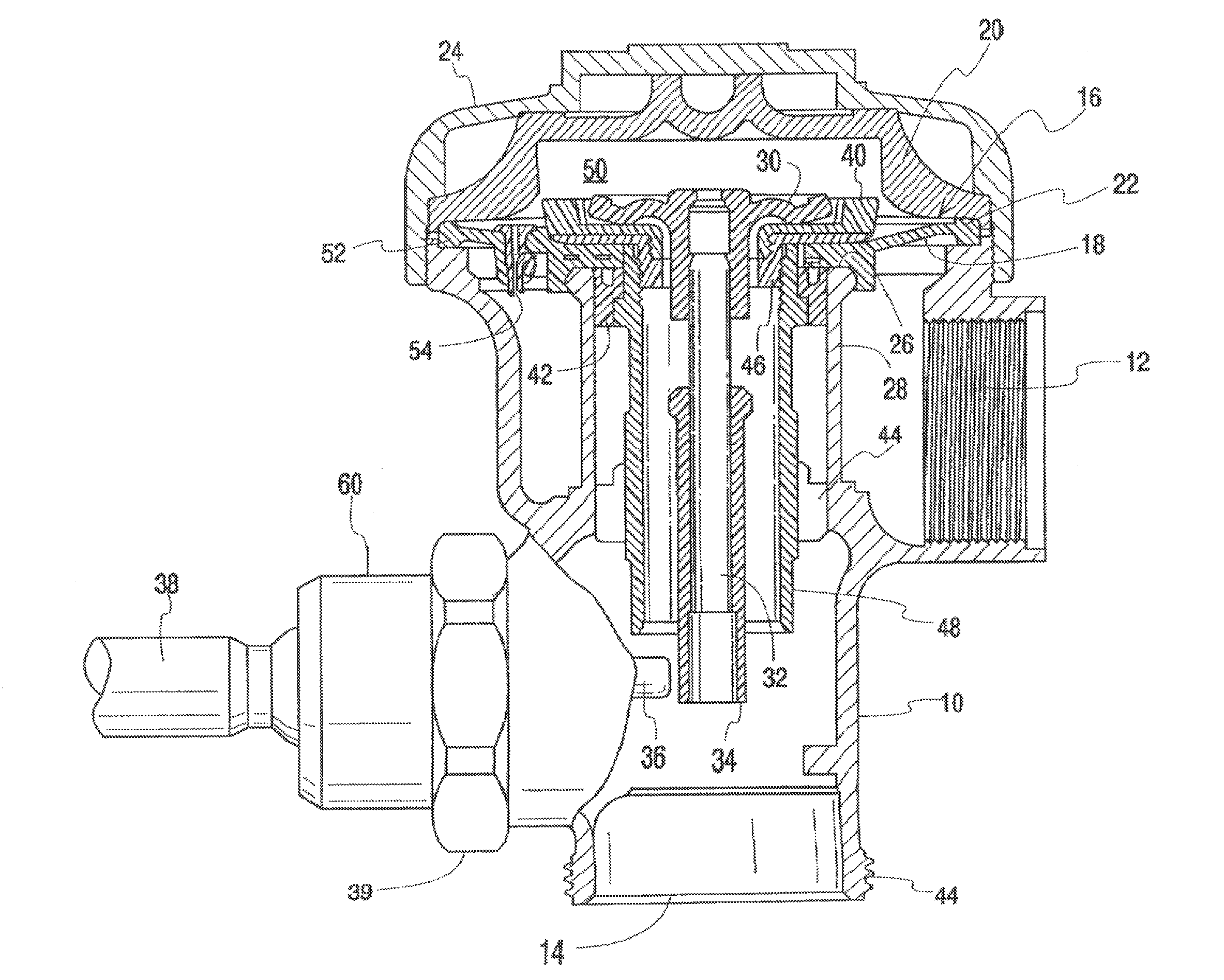
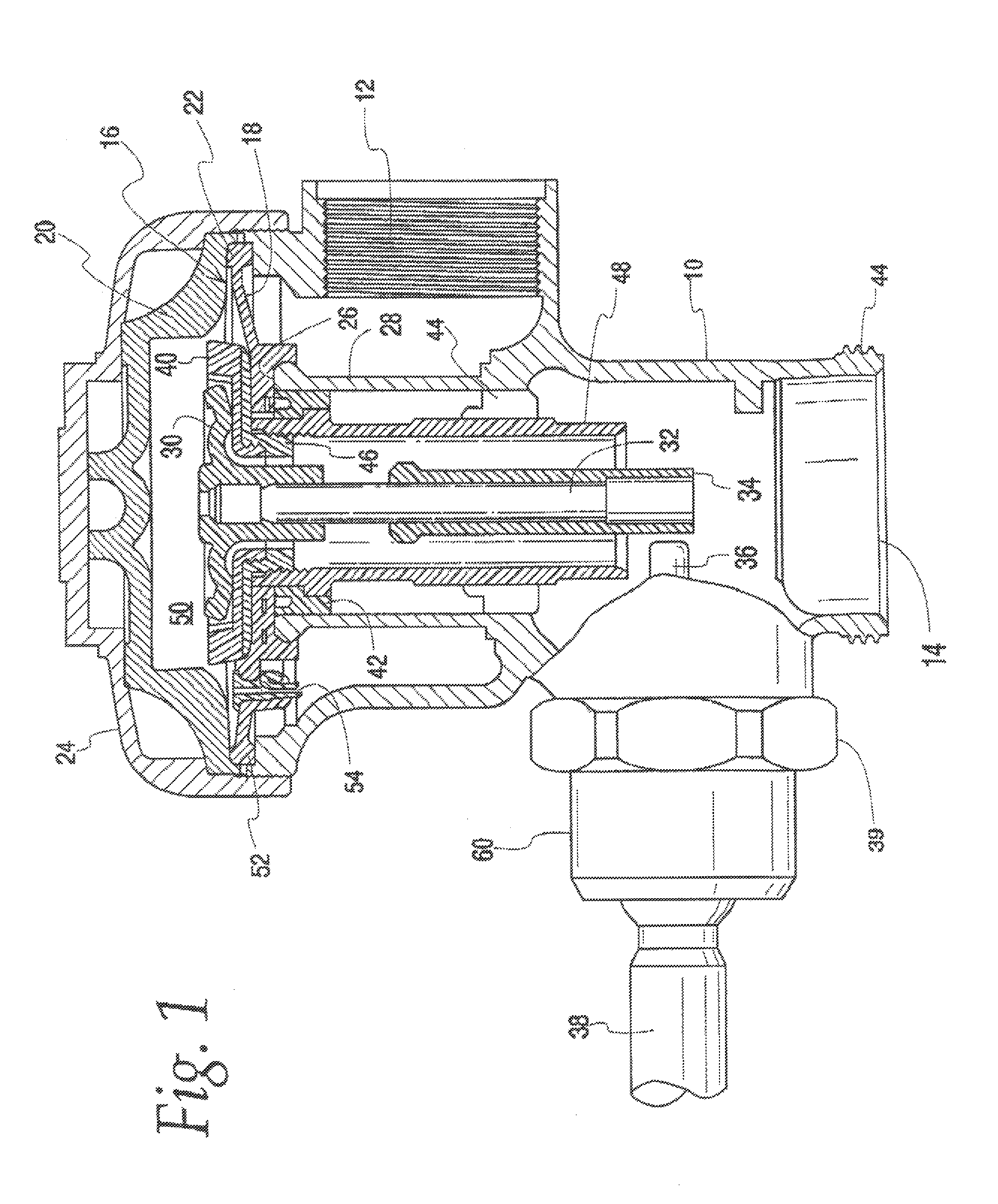
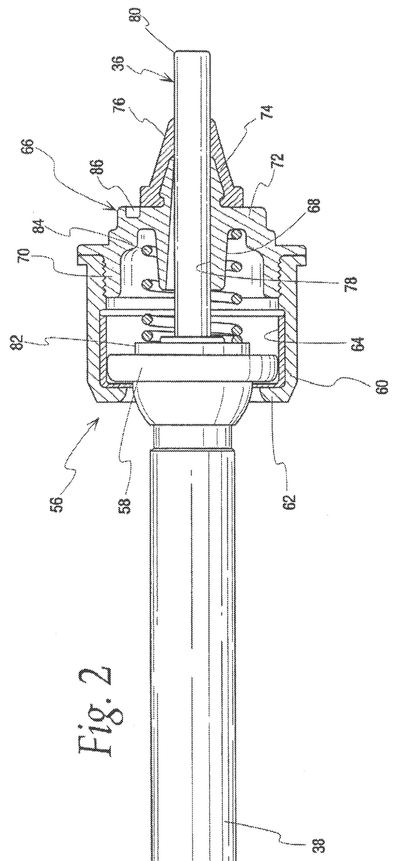
Abstract of the DisclosureA dual mode flush valve includes a handle assembly having a handle, a bushing and a plunger. The bushing has a sleeve with a passage therethrough for mounting the plunger for sliding and tilting. The passage is defined by first and second partially overlapping bores that coincide at the inner end of the sleeve and are spaced one above the other at the outer end of the sleeve. The bores define a horizontal plunger travel axis and an angled plunger travel axis. Depending on which direction the user actuates the handle the plunger will travel along one of these axes. Travel along the angled axis will lower the plunger tip, allowing earlier clearance of a relief valve and a reduced flow through the flush valve compared to actuation with the plunger travel along the horizontal axis.

Description

Detailed Description of the InventionBACKGROUND OF THE INVENTION[0001] The present invention relates to flush valves for use with plumbing fixtures such as toilets, and more specifically to improvements in the bushing of the actuating handle assembly that will provide for user-selectable, dual mode operation of the flush valve.[0002] Conservation of water resources in the use of toilets can be achieved by allowing a user to select the volume of water required to clean the fixture. For liquid waste a reduced flush volume is adequate. For solid waste a full flush is necessary. Based on the user’s determination of whether a larger or smaller flush volume is appropriate to clean the bowl, a flush valve can be operated to provide a larger or smaller volume. Flush valves of this type can be designated dual mode flush valves.[0003] The prior art includes dual mode flush valves. U.S. Patent No. 2,738,946 has a handle assembly which allows a user to choose either a low volume flush or a...

Claims


Application Information

Patent Timeline
Patent Type & Authority Applications(United States)
IPC IPC(8): F16K31/12
CPCE03D3/12F16K31/3855F16K31/60
Inventor WILSON, JOHN R.
Owner SLOAN VALVE COMPANY
Learn More