
Vapor deposition apparatus

a technology of vapor deposition apparatus and vapor deposition liquid, which is applied in the direction of chemical vapor deposition coating, electric discharge tube, coating, etc., can solve the problems of degradation of plasma uniformity and yield reduction, and achieve the effect of increasing yield and more uniform plasma

Active Publication Date: 2017-04-11
SAMSUNG DISPLAY CO LTD
View PDF23 Cites 0 Cited by
  • Summary
  • Abstract
  • Description
  • Claims
  • Application Information

AI Technical Summary

Benefits of technology

The design enhances yield by reducing the time required to stabilize voltage and plasma uniformity, preventing thermal deformation and arc discharge, resulting in more consistent thin film deposition.

Problems solved by technology

However, since a material having high stiffness, such as SUS, generally has high resistance, and thus generates much heat, and also has a slow rate of releasing heat, the temperature of an electrode is saturated, and thus it takes long to stabilize a voltage and a current, resulting in a reduction of yield.
Moreover, the electrode may be thermally deformed due to a high temperature, and the accompanying ionization of a reaction gas is locally accelerated to generate arc discharge, resulting in a degradation of the uniformity of plasma.

Method used


Image

  • Vapor deposition apparatus
  • Vapor deposition apparatus
  • Vapor deposition apparatus

Examples


Embodiment Construction

[0037]As embodiments of the present invention allow for various changes, particular embodiments will be illustrated in the drawings, and described in detail in the written description. However, this is not intended to limit the present invention to particular modes of practice, and it is to be appreciated that all changes, equivalents, and substitutes that do not depart from the spirit and technical scope of the present invention are encompassed in the present invention. In the following description of embodiments of the present invention, a detailed description of disclosed technology will not be provided if deemed to make features of embodiments of the invention obscure.

[0038]While terms such as “first,”“second,” etc., may be used to describe various components, such components must not be limited to the above terms. The above terms are used only to distinguish one component from another.

[0039]The terms used in the present specification are merely used to describe particular embod...


PUM

PropertyMeasurementUnit
thermal conductivityaaaaaaaaaa
electrical conductivityaaaaaaaaaa
voltageaaaaaaaaaa

Abstract

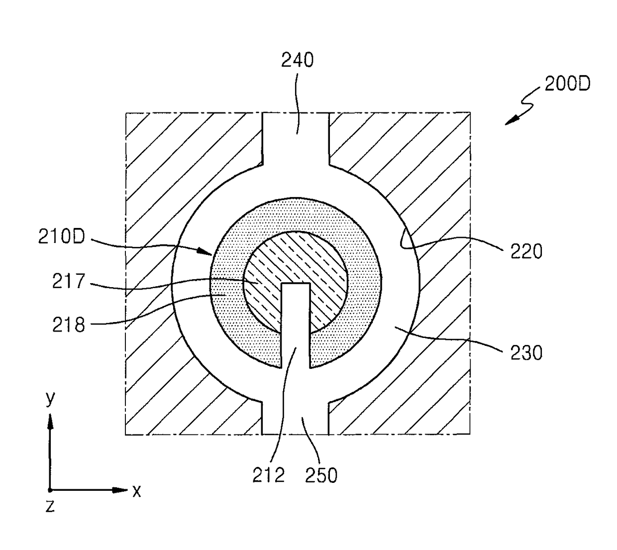
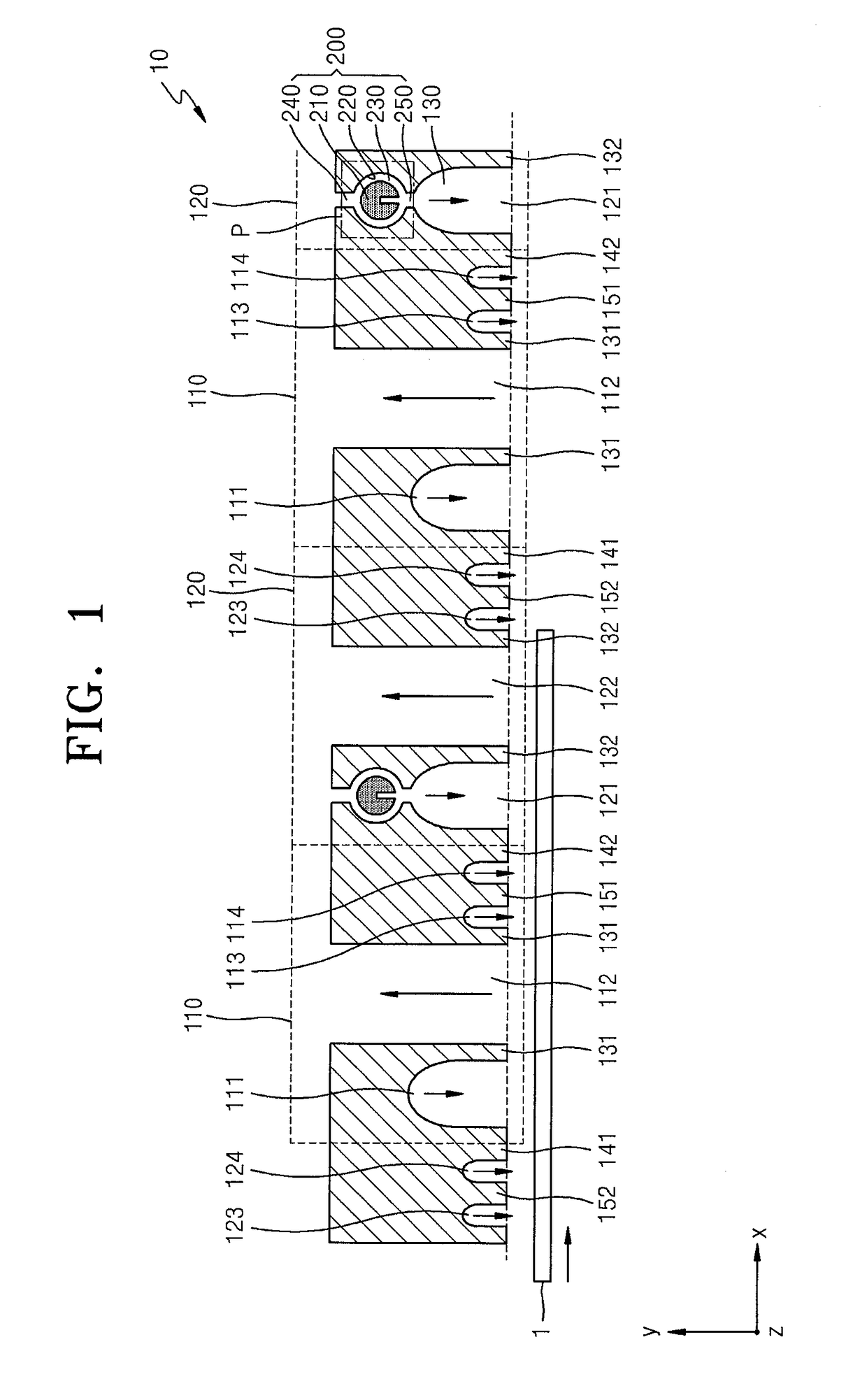
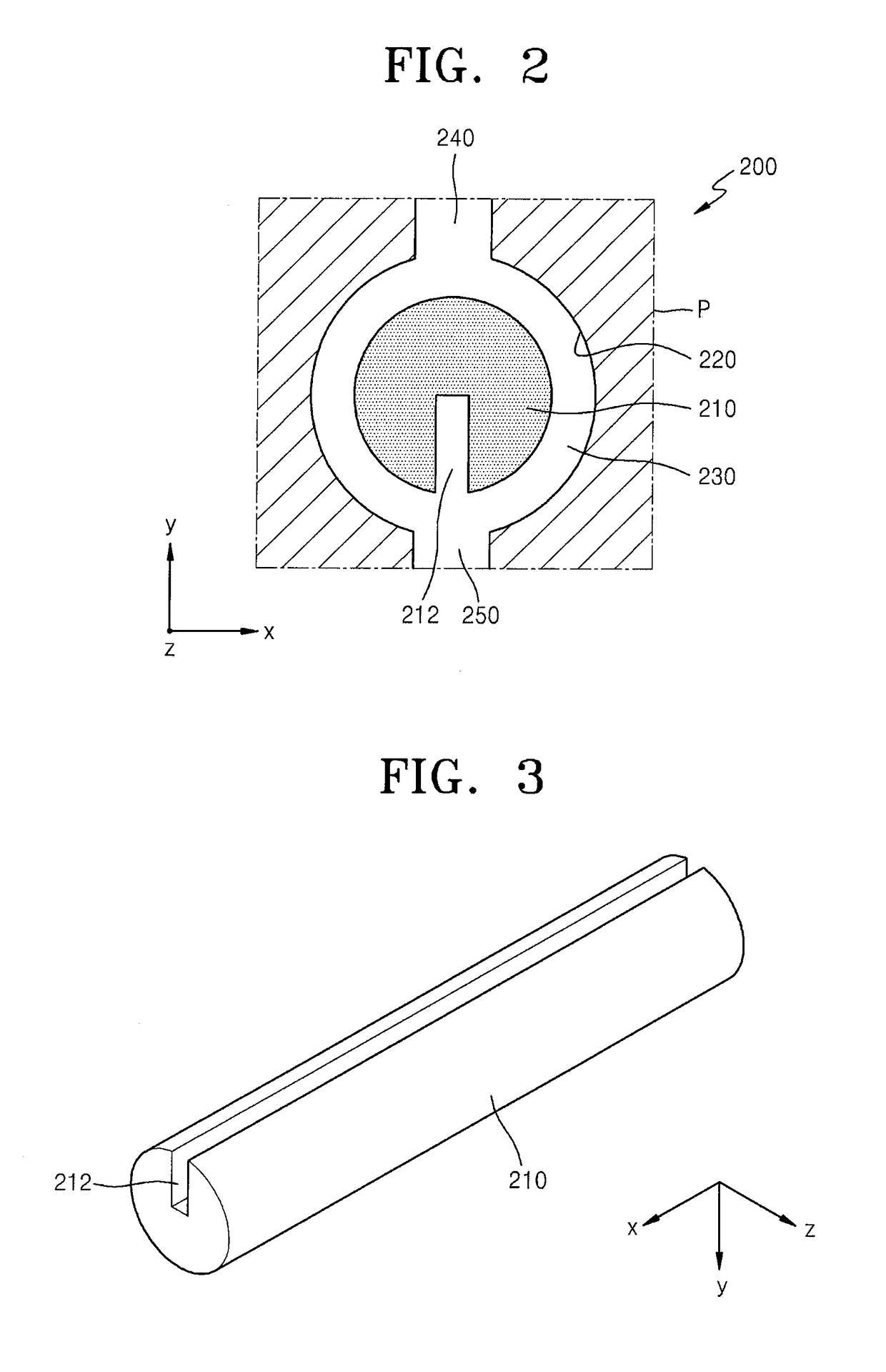
A vapor deposition apparatus including a first region including a first injection unit configured to inject a first raw material, and a second region including a second injection unit configured to inject a second raw material, wherein the second injection unit includes a plasma generation unit, wherein the plasma generation unit includes a plasma generator, a corresponding surface surrounding the plasma generator, and a plasma generation space between the plasma generator and the corresponding surface, and wherein the plasma generator has a groove in a lengthwise direction of the plasma generator.

Description

CROSS-REFERENCE TO RELATED PATENT APPLICATION[0001]This application claims priority to and the benefit of Korean Patent Application No. 10-2012-0125705, filed on Nov. 7, 2012, in the Korean Intellectual Property Office, the disclosure of which is incorporated herein in its entirety by reference.BACKGROUND[0002]1. Field[0003]Embodiments of the present invention relate to vapor deposition apparatuses.[0004]2. Description of the Related Art[0005]Semiconductor devices, display devices, and other electronic devices include a plurality of thin films. These thin films are formed using various methods, one of which is a vapor deposition method. According to a vapor deposition method, one or more gases are used as a raw material(s) to form thin films. Examples of the vapor deposition method include chemical vapor deposition (CVD), atomic layer deposition (ALD), and the like. In ALD, a raw material is injected (e.g., deposited) onto a substrate, and is then purged and pumped to absorb one or ...

Claims


Application Information

Patent Timeline
Patent Type & Authority Patents(United States)
IPC IPC(8): C23C16/50C23C16/452H01J37/32C23C16/455C23C16/54
CPCC23C16/452C23C16/45519C23C16/45536C23C16/45551C23C16/54H01J37/3244C23C16/448C23C16/50
Inventor JANG, CHEOLKIM, SEUNG-HUNSONG, SEUNG-YONGKIM, JIN-KWANG
Owner SAMSUNG DISPLAY CO LTD
Learn More