
Working medium and heat cycle system

a technology of working medium and heat cycle, which is applied in the direction of refrigeration components, light and heating apparatus, organic chemistry, etc., can solve the problems of high equipment pressure, high risk of coolant leakage out to the air, and global warming, and achieves reduced combustibility, reduced production cost, and reduced production cost

Active Publication Date: 2017-03-14
AGC INC
View PDF10 Cites 5 Cited by
  • Summary
  • Abstract
  • Description
  • Claims
  • Application Information

AI Technical Summary

Benefits of technology

[0017]The working medium of the present invention, which comprises HCFO-1224yd having a high proportion of halogen, has combustibility suppressed. Further, since it comprises HCFO-1224yd having a carbon-carbon double bond which is easily decomposed by OH radicals in the air, it has less influence over the ozone layer and has less influence over global warming. Further, since it comprises HCFO-1224yd, it provides a heat cycle system which is excellent in the cycle performance (efficiency and capacity).
[0018]The heat cycle system of the present invention, which employs the working medium of the present invention of which combustibility is suppressed, has safety secured.
[0019]Further, since it employs the working medium of the present invention excellent in the thermodynamic properties, it is excellent in the cycle performance (efficiency and capacity). Further, due to excellent efficiency, a reduction in the power consumption will be attained, and due to excellent capacity, downsizing of a system can be achieved.

Problems solved by technology

However, it is pointed out that HFCs may cause global warming.
Further, in an automobile air conditioner, the coolant is highly likely to leak out to the air e.g. from a connection hose or a bearing.
However, with carbon dioxide, the equipment pressure tends to be extremely high as compared with HFC-134a, and accordingly there are many problems to be solved in application to all the automobiles.
HFC-152a has a range of inflammability, and has a problem for securing the safety.
However, in a case where HCFO-1233zd(E) is used as a working medium for heat cycle, it is insufficient in the cycle performance (capacity).

Method used


Image

  • Working medium and heat cycle system
  • Working medium and heat cycle system
  • Working medium and heat cycle system

Examples


example 1

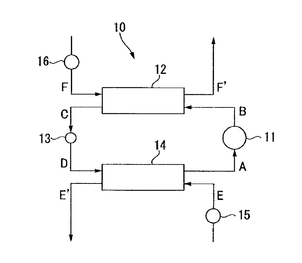
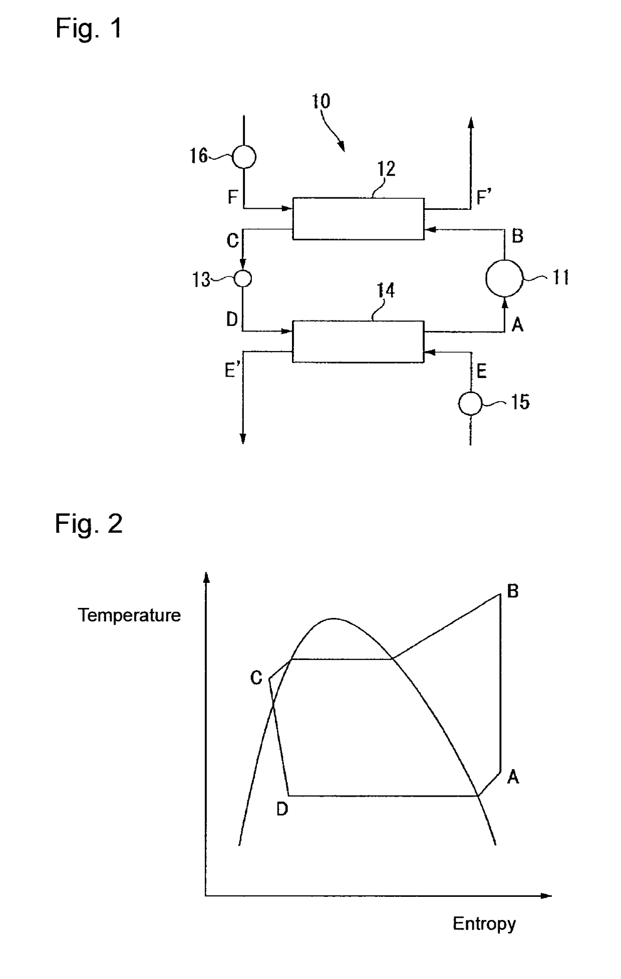
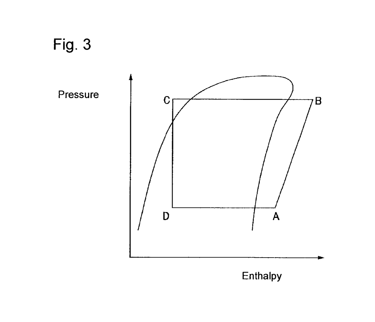
[0114]The refrigerating cycler performance (the refrigerating capacity and the coefficient of performance) was evaluated in a case where HCFO-1224yd, 1,1-dichloro-2,2,2-trifluoroethane (HCFC-123), 1,1,1,3,3-pentafluoropropane (HFC-245fa) or HFC-134a as a working medium was applied to a refrigerating cycle system 10 shown in FIG. 1.

[0115]The evaporation temperature of the working medium in an evaporator 14, the condensing temperature of the working medium in a condenser 12, the supercooling degree of the working medium in the condenser 12 and the degree of superheat of the working medium in the evaporator 14 were temperatures as identified in Table 1.

[0116]Based on the refrigerating cycle performance of HFC-245fa, the relative performance (each working medium / HFC-245fa) of the refrigerating cycle performance (the refrigerating capacity and the coefficient of performance) of each working medium based on HFC-245fa was obtained. The results of each working medium are shown in Table 1.

[0...

example 2

[0119]The refrigerating cycle performance (the refrigerating capacity and the coefficient of performance) was evaluated in a case where a working medium comprising HCFO-1224yd and a HFO as identified in Table 2 was applied to a refrigerating cycle system 10 shown in FIG. 1.

[0120]Evaluation was carried out by setting the average evaporation temperature of the working medium in an evaporator 14 to be 0° C., the average condensing temperature of the working medium in a condenser 12 to be 50° C., the supercooling degree of the working medium in the condenser 12 to be 5° C., and the degree of superheat of the working medium in the evaporator 14 to be 5° C.

[0121]Based on the refrigerating cycle performance of HFC-245fa, the relative performance (each working medium / HFC-245fa) of the refrigerating cycle performance (the refrigerating capacity and the coefficient of performance) of each working medium based on HFC-245fa was obtained. The results of each working medium are shown in Table 2.

[...

example 3

[0124]The refrigerating cycle performance (the refrigerating capacity and the coefficient of performance) was evaluated in a case where a working medium comprising HCFO-1224yd and a HCFC or a HFC as identified in Table 3 or 4 was applied to a refrigerating cycle system 10 shown in FIG. 1.

[0125]Evaluation was carried out by setting the average evaporation temperature of the working medium in an evaporator 14 to be 0° C., the average condensing temperature of the working medium in a condenser 12 to be 50° C., the supercooling degree of the working medium in the condenser 12 to be 5° C., and the degree of superheat of the working medium in the evaporator 14 to be 5° C.

[0126]Based on the refrigerating cycle performance of HFC-245fa, the relative performance (each working medium / HFC-245fa) of the refrigerating cycle performance (the refrigerating capacity and the coefficient of performance) of each working medium based on HFC-245fa was obtained. The results of each working medium are sho...


PUM

PropertyMeasurementUnit
global warming potentialaaaaaaaaaa
sizeaaaaaaaaaa

Abstract

To provide a working medium for heat cycle, of which combustibility is suppressed, which has less influence over the ozone layer, which has less influence over global warming and which provides a heat cycle system excellent in the cycle performance (efficiency and capacity), and a heat cycle system, of which the safety is secured, and which is excellent in the cycle performance (efficiency and capacity).A working medium for heat cycle comprising 1-chloro-2,3,3,3-tetrafluoropropene is employed for a heat cycle system (such as a Rankine cycle system, a heat pump cycle system, a refrigerating cycle system 10 or a heat transport system).

Description

TECHNICAL FIELD[0001]The present invention relates to a working medium and a heat cycle system employing the working medium.BACKGROUND ART[0002]Heretofore, as a working medium for heat cycle such as a coolant for a refrigerator, a coolant for an air conditioner, a working fluid for power generation system (such as exhaust heat recovery power generation), a working medium for a latent heat transport apparatus (such as a heat pipe) or a secondary cooling medium, a chlorofluorocarbon (CFC) such as chlorotrifluoromethane or dichlorodifluoromethane or a hydrochlorofluorocarbon (HCFC) such as chlorodifluoromethane has been used. However, influences of CFCs and HCFCs over the ozone layer in the stratosphere have been pointed out, and their use are regulated at present.[0003]Accordingly, as a working medium for heat cycle, a hydrofluorocarbon (HFC) which has less influence over the ozone layer, such as difluoromethane (HFC-32), tetrafluoroethane or pentafluoroethane, has been used. However,...

Claims


Application Information

Patent Timeline
Patent Type & Authority Patents(United States)
IPC IPC(8): C09K5/04F25B9/00
CPCC09K5/044C09K5/045F25B9/002C09K2205/12C09K2205/126C09K2205/122C07C21/18F25B1/00F25B31/002F25B43/003F25B2500/222
Inventor FUKUSHIMA, MASATO
Owner AGC INC
Learn More