
Segmentally rigid suture and suturing technique

a segmental rigid and suture technology, applied in the field of segmental rigid suture and suturing technique, can solve the problems of affecting the function of the suture, so as to limit the compressive load

Active Publication Date: 2017-03-07
DEAN & WEBB
View PDF67 Cites 5 Cited by
  • Summary
  • Abstract
  • Description
  • Claims
  • Application Information

AI Technical Summary

Benefits of technology

[0011]The suture device affixes soft tissue with a stitch having at least one suture pass into the soft tissue, and the at least one segment disposes adjacent an outside surface of the soft tissue in the stitch adjacent the at least one suture pass. So situated, the at least one segment supports the suture device against the outside surface of the soft tissue and limits a compressive load on the soft tissue by the suture at the at least one suture pass. In this way, the segment resists the pull-through of the suture in the soft tissue.
[0012]Rather than just one pass, the stitch can have at least two passes into the soft tissue. In this instance, the at least one segment can be disposed adjacent the outside surface of the soft tissue in the stitch adjacent the at least two suture passes. Then, the at least one segment supports the suture device against the outside surface of the soft tissue and limits the compressive load by the suture on the soft tissue between the at least two suture passes.
[0016]As hinted to previously, the at least one segment on the device limits a first portion of the suture at a first end of the at least one segment from moving toward a second portion of the suture at a second end of the at least one segment. Thus, when the at least one segment disposes adjacent soft tissue and a first portion of the suture passes into the soft tissue at a suture point, the at least one segment can limit tearing of the soft tissue by the first portion of the suture at the suture point because the segment limits the compressive load the suture puts on the soft tissue. Also, the at least one segment can limit tearing of the soft tissue by a portion of the suture when the suture is disposed against an outside of the segment.
[0018]The suture device in this stitch limits a compressive load of the suture on the soft tissue between at least one of the first suture points and the intermediate point by positioning the at least one segment disposed on the suture device against an outside surface of at least one side of the soft tissue between the suture points. In some embodiments, the suture device can have at least two rigid segments or elements. Thus, a first portion of the suture device on one side of the soft tissue can be supported with one rigid segment on the suture device against the soft tissue between the first and intermediate suture points. Likewise, a second portion of the suture device on the one side of the soft tissue can be supported with the same or different rigid segment on the suture device against the soft tissue between the second and intermediate suture points. In this way, the suture device in the stitch limits the compressive load on the soft tissue by the suture between both of the first suture points and the intermediate suture point by positioning the one or more segments against the outside surface of the one side of the soft tissue between the suture points.

Problems solved by technology

In the case of both of these tears, such a torn rotator cuff can lead to pain, weakness, and loss of function.
Failure of the repair is often instigated on the soft tissue site where, typically, suture is passed through the tendon in a number of ways.
Failure occurs when the suture slices through the tendon while under tension.

Method used


Image

  • Segmentally rigid suture and suturing technique
  • Segmentally rigid suture and suturing technique
  • Segmentally rigid suture and suturing technique

Examples


Embodiment Construction

[0076]The subject matter of the present disclosure overcomes the shortcomings of current soft tissue repair techniques by disposing rigid components on suture, enabling the device to resist both tensile and compressive loads. For illustrative purposes, embodiments of the present disclosure and associated methods are described for use to repair rotator cuff tears. The techniques shown are compatible with arthroscopic surgery, however, it should be noted that those skilled in the art will recognize that the teachings of the present disclosure could use non-arthroscopic techniques to repair the soft tissue injuries without departing from the spirit or scope of the present invention. Those skilled in the art will recognize that the present disclosure can be used to repair other soft tissue injuries without departing from the spirit or scope of the present invention.

[0077]Before turning to the particular stitches disclosed herein for use in repairing soft tissue injuries, discussion firs...


PUM


Abstract

The suture device of the present disclosure disposes rigid components on suture, enabling the device to resist tensile and compressive loads and to protect soft tissue from suture pull-through. The suture device generally comprises of at least one rigid segment as well as a standard high tensile strength suture to create a segmentally rigid suture device. The at least one rigid segment may be comprised of any of a number of materials that are appropriate for use in the human body and provide the desired strength and stiffness for a particular application. Although the segmentally rigid suture device could be used with any prior art suture configuration, a grip stitch, a knot tying grip stitch, a straight-line grip stitch, and a reverse straight-line grip stitch suture configuration are described.

Description

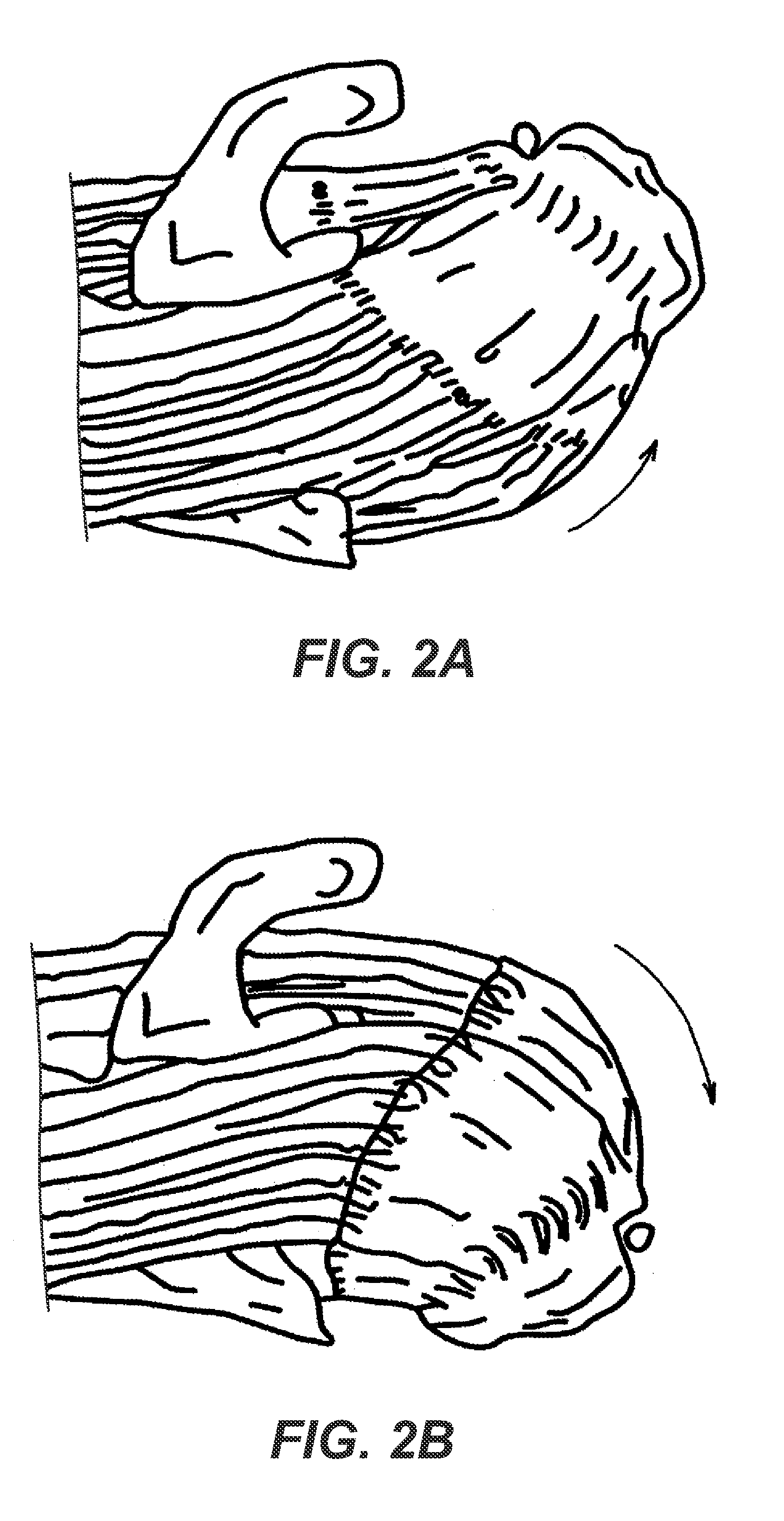
CROSS-REFERENCE TO RELATED APPLICATIONS[0001]This application claims the benefit of U.S. Provisional Appl. No. 61 / 640,997, filed 1 May 2012, which is incorporated herein by reference.BACKGROUND OF THE DISCLOSURE[0002]Tearing or avulsion of soft tissue from bone is a relatively common type of injury, especially in sports, and can occur in many types of orthopedic injuries, such as torn or ruptured tendons and / or ligaments. In the shoulder, for example, portions of the rotator cuff tendons can tear within themselves or avulse from their insertion into the bone. FIGS. 1A-1B show superior views of a shoulder having a typically torn rotator cuff. Here, the tear is associated with the supraspinatus tendon as it inserts into the humerus. The subscapularis tendon and the coracoid process are also shown in FIG. 1A for reference.[0003]The tear 10 shown in FIG. 1A is categorized as a simple tear because the tear branches normal to the muscle fibers, while the tear in FIG. 1B branches in both p...

Claims


Application Information

Patent Timeline
Patent Type & Authority Patents(United States)
IPC IPC(8): A61B17/04A61B17/06
CPCA61B17/06166A61B17/0401A61B17/0491A61B17/0469A61B2017/044A61B2017/0406A61B2017/0408A61B2017/0414A61B2017/0464A61B2017/06176
Inventor DEAN, JOHN C.WEBB, JONATHAN H.
Owner DEAN & WEBB
Learn More