Microwave heating device
a heating device and microwave technology, applied in microwave heating, electrical/magnetic/electromagnetic heating, electrical apparatus, etc., can solve the problems of non-uniform microwave electromagnetic field distribution and inability to heat uniform microwave objects
- Summary
- Abstract
- Description
- Claims
- Application Information
AI Technical Summary
Benefits of technology
Problems solved by technology
Method used
Image
Examples
first embodiment
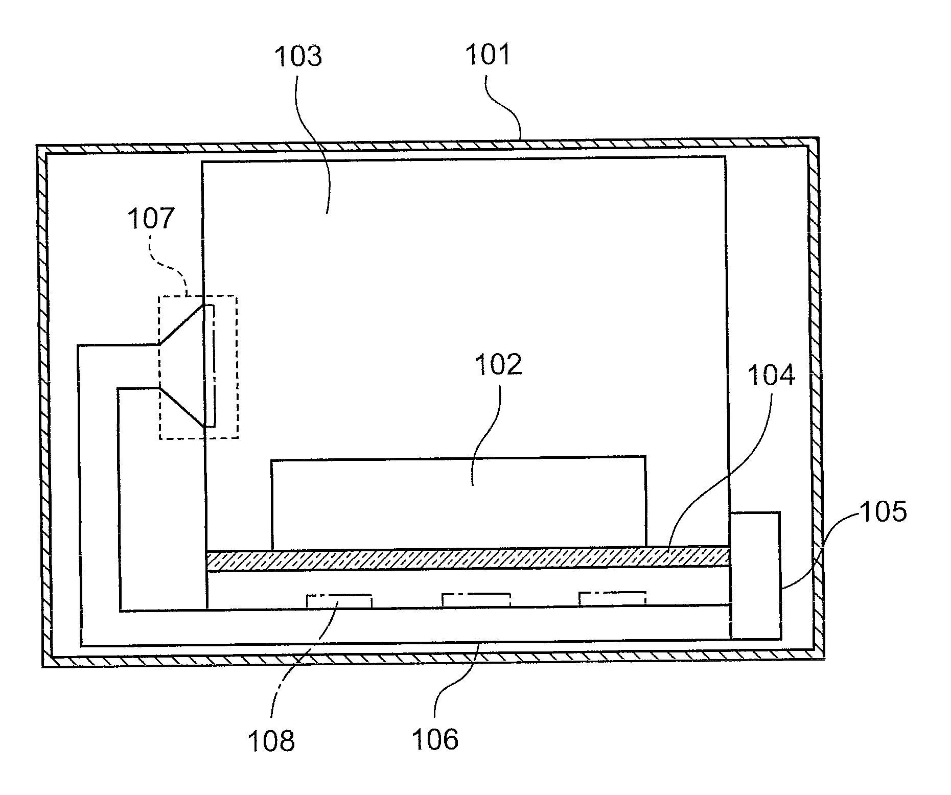
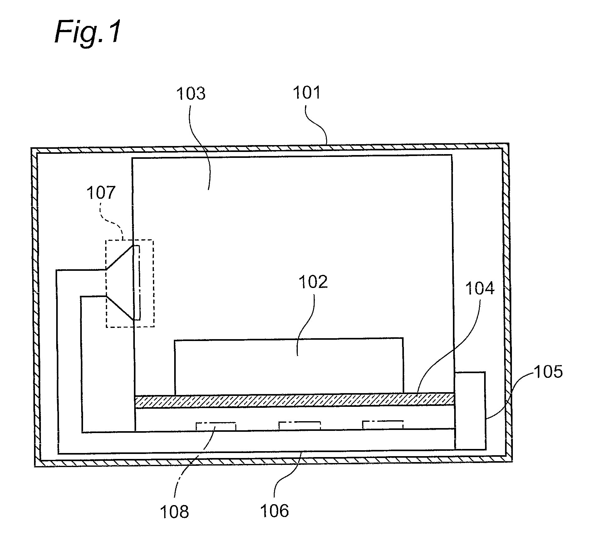
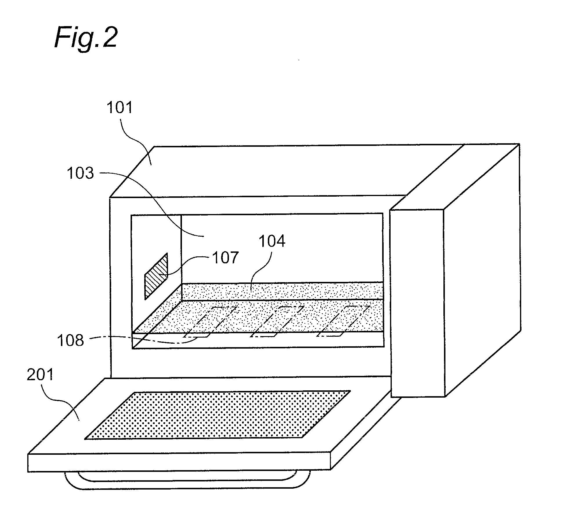
[0047]FIG. 1 is a cross-sectional view schematically illustrating the structure of a microwave oven as a microwave heating device according to a first embodiment of the present invention. Referring to FIG. 1, “101” designates a casing, “102” designates an object to be heated, “103” designates a heating chamber for housing the object 102 to be heated in the chamber, “104” designates a placement portion for placing the object 102 to be heated on the portion, “105” designates a microwave supply portion for supplying microwaves to the heating chamber 103, “106” designates a waveguide tube for propagating, to the heating chamber 103, microwaves supplied from the microwave supply portion 105, “107” designates a heating-chamber input portion extended toward the heating chamber 103 from the termination end of the waveguide tube 106 in the microwave propagation direction, and “108” designates microwave radiating portions for radiating microwaves propagating through the waveguide tube 106, to...
second embodiment
[0060]Hereinafter, a microwave heating device according to a second embodiment of the present invention will be described. The microwave heating device according to the second embodiment is different from the microwave heating device according to the aforementioned first embodiment, in that microwave radiating portions are structured to radiate circularly-polarized waves.
[0061]In the following description about the microwave heating device according to the second embodiment, components having the same functions and structures as those of the components of the microwave heating device according to the first embodiment will be designated by the same reference characters, and the description of the first embodiment will be applied to the detailed description of the second embodiment. Further, fundamental operations according to the second embodiment are similar to the operations according to the aforementioned first embodiment and, therefore, in the following description, different ope...
third embodiment
[0068]Hereinafter, a microwave heating device according to a third embodiment of the present invention will be described. The microwave heating device according to the third embodiment is different from the microwave heating device according to the aforementioned second embodiment, in terms of the structures of microwave radiating portions.
[0069]In the following description about the microwave heating device according to the third embodiment, components having the same functions and structures as those of the components of the microwave heating devices according to the first and second embodiments will be designated by the same reference characters, and the descriptions of the first and second embodiments will be applied to detailed description of the description of the third embodiment. Further, fundamental operations according to the third embodiment are similar to the operations according to the aforementioned first and second embodiments and, therefore, in the following descript...
PUM
 Abstract
Description
Claims
Application Information
 - R&D
- Intellectual Property
- Life Sciences
- Materials
- Tech Scout
- Unparalleled Data Quality
- Higher Quality Content
- 60% Fewer Hallucinations
Browse by: Latest US Patents, China's latest patents, Technical Efficacy Thesaurus, Application Domain, Technology Topic, Popular Technical Reports.
© 2025 PatSnap. All rights reserved.Legal|Privacy policy|Modern Slavery Act Transparency Statement|Sitemap|About US| Contact US: help@patsnap.com


