
System for accurate measurement of vehicle speeds for low speed industrial applications

a technology for industrial applications and accurate measurement, applied in the direction of transportation and packaging, instruments, using reradiation, etc., can solve the problems of assuming vehicle speed, waste and inefficiency, unnecessary labor, etc., and achieve the effect of precise speed determination at the point of measuremen

Inactive Publication Date: 2017-02-21
KANAWHA SCALES & SYST
View PDF18 Cites 0 Cited by
  • Summary
  • Abstract
  • Description
  • Claims
  • Application Information

AI Technical Summary

Benefits of technology

This patent describes an invention that allows for precise and responsive speed measurement of low-speed vehicles in relation to bulk material processing operations. The invention uses a laser / receiving sensor unit that is mounted perpendicular to the line of vehicle travel to measure the speed of a slow-moving target vehicle. The invention has the advantage of being able to determine precise speeds even at very low speeds. Overall, this invention provides a more efficient and accurate method for speed measurement in logistical operations.

Problems solved by technology

Where the control center / station is electronically connected to an associated bulk material processing device adapted for kinetic as opposed to static operations, loading / unloading / coating application, etc., waste and inefficiencies result from assuming vehicle speed.
For example, when the speed of a railcar is estimated or assumed, it may be overloaded resulting in spillage if it passes too slowly through a loading facility.
Such incomplete applications may result in unnecessary labor to remove frozen material and / or even lead to violations of applicable transportation regulations.
Conversely, if the assumed speed varies in the context of loading, a vehicle may be overloaded, under loaded, or unevenly distributed.
In the context of applying additives, additives may be wasted or placed imprecisely (economically and environmentally undesirable).
The prior art contains numerous examples of speed and directional sensing systems based on discrete sensors, such as photo-eyes or rail track switches, However, such systems due to sensor spacing, can only update such information periodically.
While this method of measuring speed is somewhat reasonable for overall or general speed determination, such systems are inadequate to make real-time speed determinations during critical stages.
More specifically, reliance on sets of static discrete sensors (usually photoelectric sensors or track mounted switches) installed at known distances from each other may not be accurate when a railcar stops or is subject to speed irregularities between two sensors.
Even reliance on sophisticated computers, e.g., a PLC (Programmable Logic Controller) control system that monitor the on / off state of the static sensors and calculate the time elapsed between subsequent sensor on / off states to process the periodic data does not overcome the real-time detection issue.
Such a situation can be problematic particularly in cases such as when the measured speed information is provided to a flow control device or a loading chute in a bulk material processing station.
But such a “solution” introduces additional infrastructure needs in wiring, sensors, PLC control points, etc. such that the system becomes expensive, difficult to operate, and requires considerably labor to maintain.
Furthermore, although to a lesser extent, such a periodic sensing array still possesses similar limitations to those described above.
However, at sub-5 miles per hour speeds typically associated with bulk material processing operations, Doppler shift detection is neither meaningfully measurable nor capable of providing the required accuracy for vehicle speed detection.
Consequently, in the context of bulk material transport and processing equipment (loaders, unloaders, sprayers, etc.), particularly in the case of a slow moving train of coupled railcars, such conventional speed measuring devices are ineffective and not reliably usable for vehicle / bulk material processing equipment coordination.
Neither of these prior art systems are capable of determining the specific velocity of an individual railcar within a long train where such velocity can vary at any discrete point in time due to train stretching (tension) or bunching (compression) effects caused, for example, by coupler slack considerations.
Therefore, locomotive or whole train based speed determination whether from a vehicle mounted device or remote tracking device, e.g., GPS, are not sufficiently applicable or accurate for usage during critical stages of bulk material processing operations.
While representing an improvement, this system does not address the specific problem associated precise speed measurement of an individual rail-car in a moving train associated with a bulk material processing station.

Method used


Image

  • System for accurate measurement of vehicle speeds for low speed industrial applications
  • System for accurate measurement of vehicle speeds for low speed industrial applications
  • System for accurate measurement of vehicle speeds for low speed industrial applications

Examples


Embodiment Construction

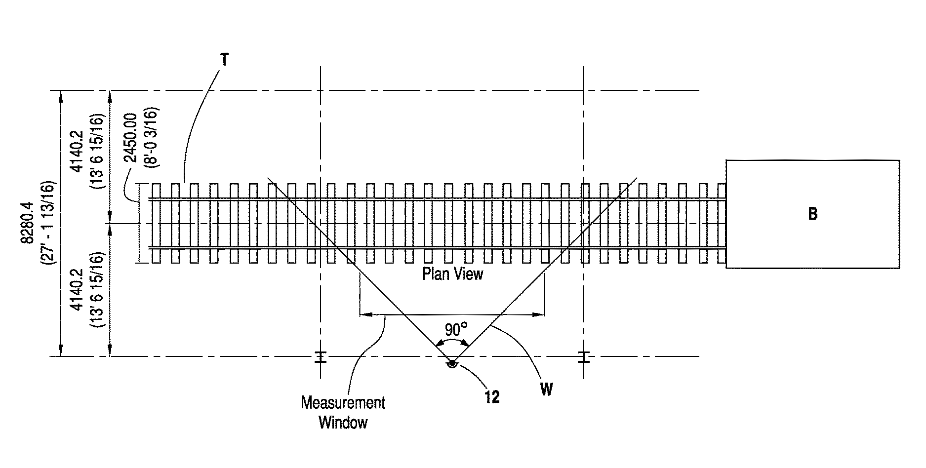
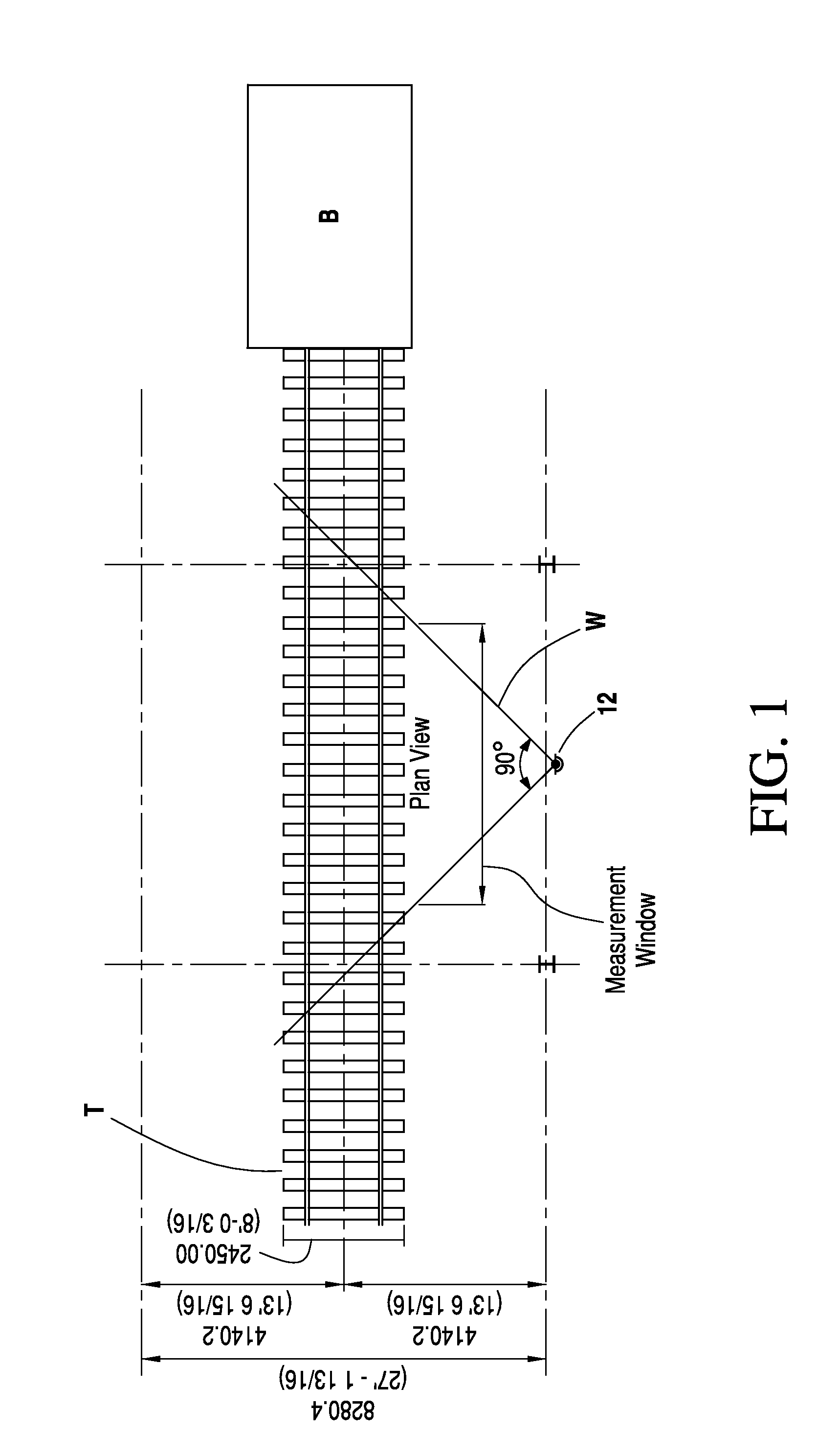
[0032]FIG. 1 depicts a plan view of the positioning of a scanning laser detector 12 of the invention relative to a railroad track T proximate to a bulk material processing station B. Preferably, the scanning laser detector 12 is fixed to be perpendicular to the track and between 10 to 20 feet (3-6 meters) from the track midline. More preferably to provide a measurement window W with a 90° arc, the scanning laser detector 12 is located 13.5 feet (˜4 meters) from the track mid-line.

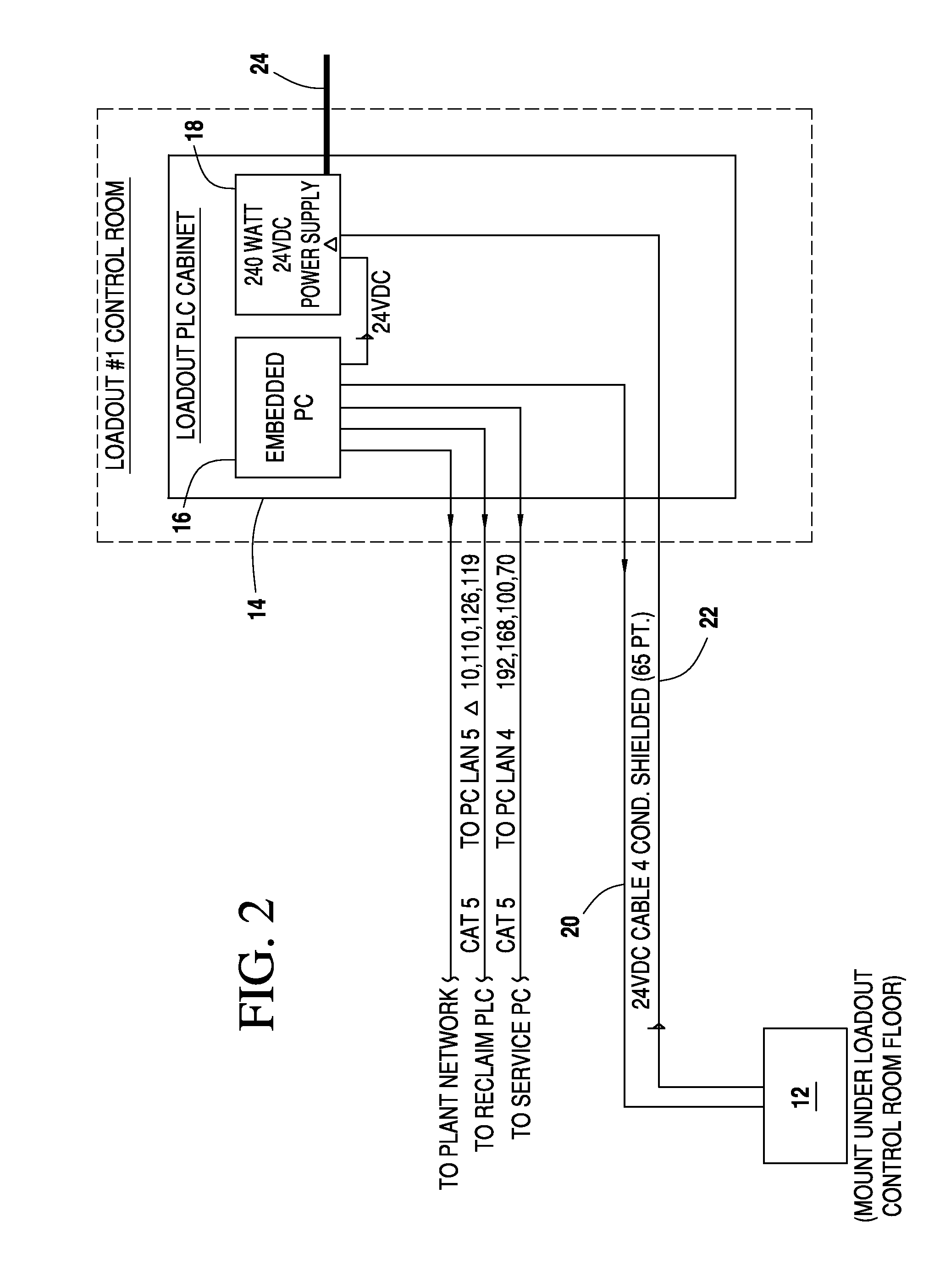
[0033]FIG. 2 illustrates a combination of components, all of which are commercially available, utilized for a typical installation. The scanner laser sensor unit 12 is of the type such as that available from SICK AG Waldkirch (Germany) as a Model LMS511 relying on time-of-flight technology for non-contact measurement. The scanner laser sensor unit 12 includes a heater and other sensitive electrical components and is contained in a sealed housing suitable for outdoor environments. Preferably the laser / receiv...


PUM


Abstract

A continuous scanning side laser detector system and method for real time, instantaneous accurate speed and direction measurement of a slow moving bulk material transport vehicle through a bulk material processing station.

Description

PRIORITY CLAIM[0001]This application claims the benefit of U.S. Provisional Application Ser. No. 61 / 787,974 filed on Mar. 15, 2013 which is incorporated herein by reference.FIELD OF INVENTION[0002]This invention relates to the precise and responsive measurement of slow speed bulk material transport vehicles when associated with bulk material processing stations and, more particularly, with precise measurement of the speed of a specific individual railcar in a train moving in a straight line.BACKGROUND[0003]The measurement of speed of an individual railcar in a moving train proximate to a bulk material processing station is not addressed by existing systems. Bulk material processing, including loading, unloading, and / or cargo spray treatments, etc., involving a moving railcar requires extreme precision to avoid inefficiencies, errors and / or wastage. Where the control center / station is electronically connected to an associated bulk material processing device adapted for kinetic as opp...

Claims


Application Information

Patent Timeline
Patent Type & Authority Patents(United States)
IPC IPC(8): B61L27/00G01S17/88G01S7/497G01S7/48G01S17/42G01S17/58G01P5/18
CPCB61L27/0077G01P5/18G01S7/4808G01S7/497G01S17/42G01S17/58G01S17/88B61L27/40
Inventor BENNETT, DUANE LEEBARKER, JR., ROBERT EMILFOLEY, JAMES TROY
Owner KANAWHA SCALES & SYST
Learn More