
Semiconductor structure with a spacer layer

a spacer layer and semiconductor technology, applied in the direction of semiconductor devices, electrical equipment, transistors, etc., can solve the problems of high density of defect states of dry plasma etching

Active Publication Date: 2017-01-03
FINWAVE SEMICON INC
View PDF12 Cites 7 Cited by
  • Summary
  • Abstract
  • Description
  • Claims
  • Application Information

AI Technical Summary

Benefits of technology

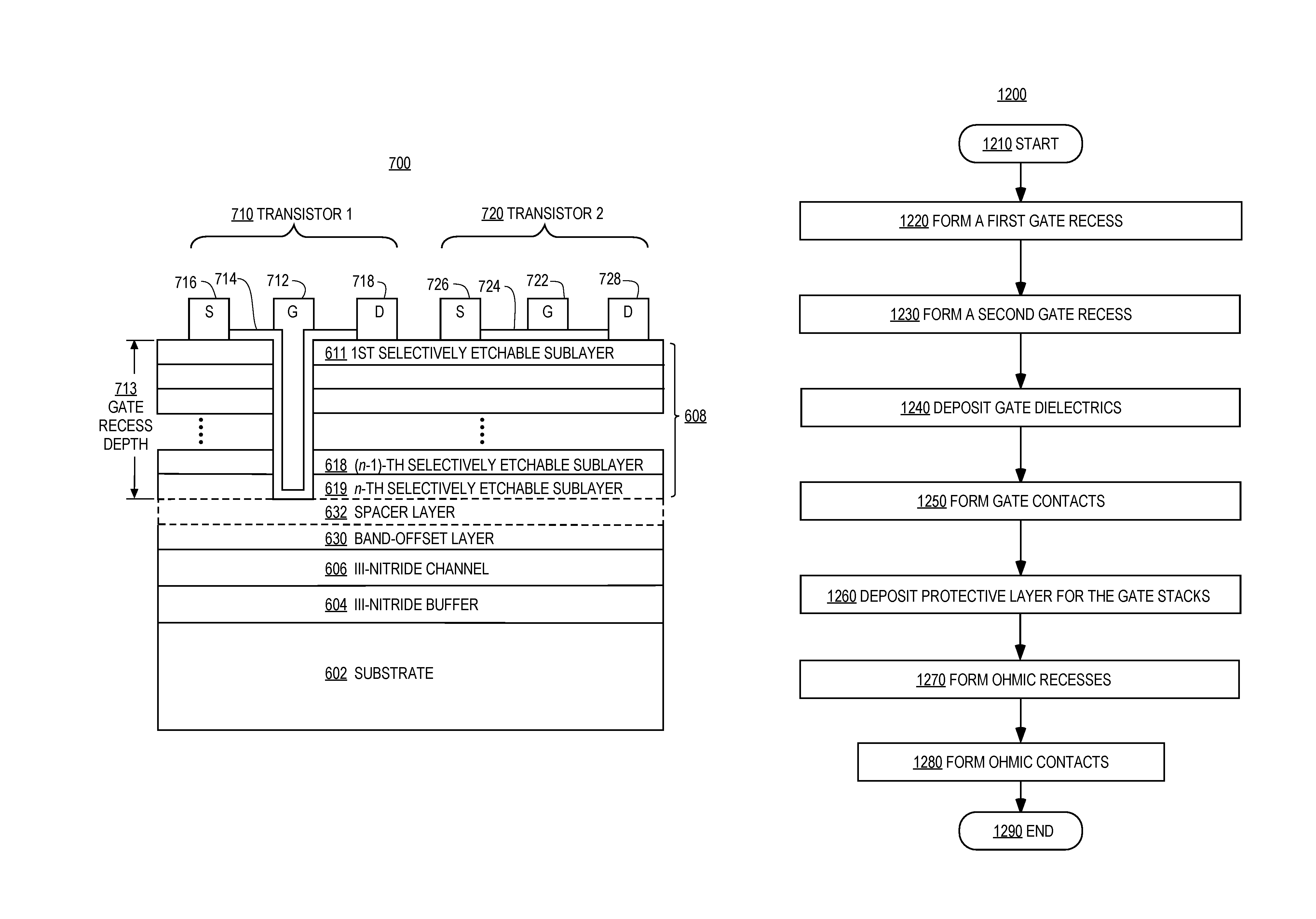
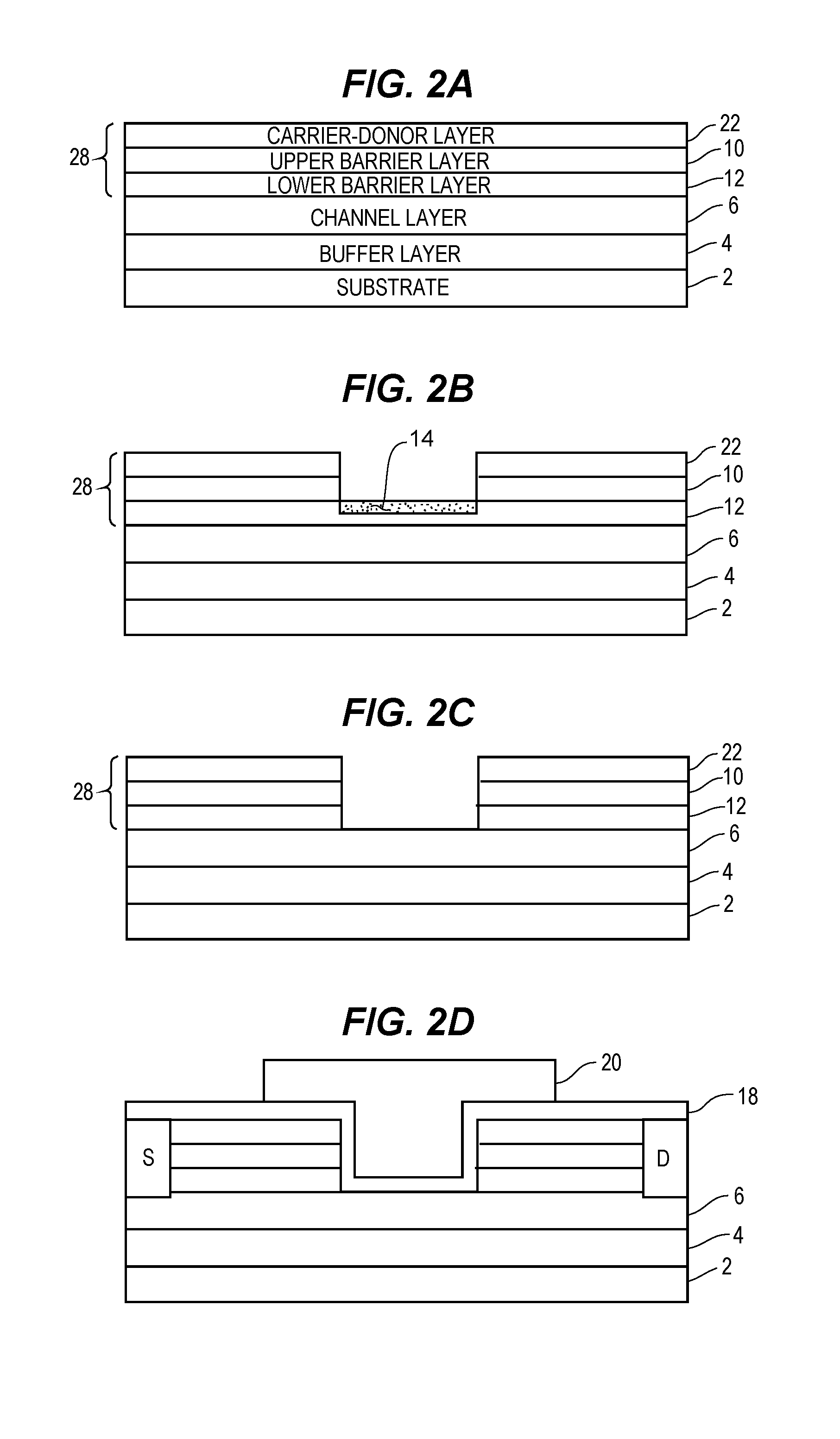
The present invention provides a semiconductor structure and method for fabricating III-nitride transistors with different threshold voltages on a common substrate. The structure includes a channel layer, a band-offset layer, a spacer layer, and a cap layer. The cap layer has at least two sublayers that are selectively etchable with respect to sublayers immediately above and below. The sublayer has a non-zero Al content and the band-offset layer has a non-zero Al content. The structure also includes a carrier-donor layer and a gate region with a gate dielectric material and ohmic contacts. The invention allows for the fabrication of semiconductor structures with different threshold voltages on a common substrate.

Problems solved by technology

Silicon's limited critical electric field and relatively high resistance make currently available commercial power devices, circuits, and systems bulky, heavy, with further constraints on operating frequencies.
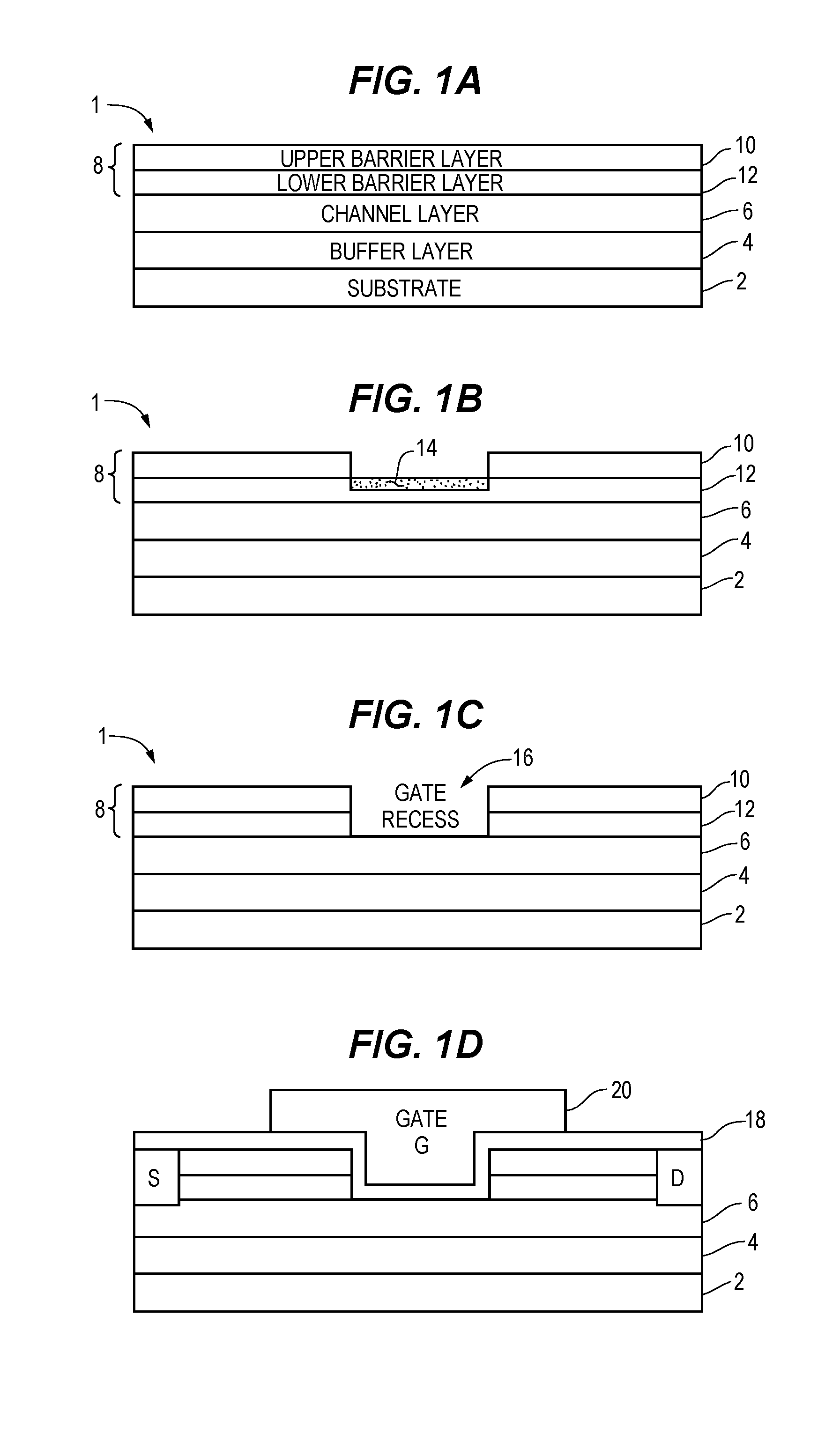
However, dry plasma etching is prone to plasma-induced damage and etch-based process variations.
Plasma damage creates a high density of defect states and degrades channel mobility in the recessed region.
Variations in the plasma etch rate make it difficult to control recess depth precisely by timed etching, which causes a variation in transistor parameters such as the transconductance and threshold voltage.
Thus, dry plasma etching-based gate recess techniques are insufficient for the integration of different types of transistors with different target threshold voltages on the same substrate.
Therefore, in view of the aforementioned practicalities and difficulties, there is an unsolved need to monolithically integrate III-N transistors with different threshold voltages on a common substrate.

Method used


Image

  • Semiconductor structure with a spacer layer
  • Semiconductor structure with a spacer layer
  • Semiconductor structure with a spacer layer

Examples


Embodiment Construction

[0039]In the following description, for purposes of explanation, numerous specific details are set forth in order to provide a thorough understanding of the invention. It will be apparent, however, to one skilled in the art that the invention can be practiced without these specific details. In other instances, structures, devices, activities, and methods are shown using schematics, use cases, and / or flow diagrams in order to avoid obscuring the invention. Although the following description contains many specifics for the purposes of illustration, anyone skilled in the art will appreciate that many variations and / or alterations to suggested details are within the scope of the present invention. Similarly, although many of the features of the present invention are described in terms of each other, or in conjunction with each other, one skilled in the art will appreciate that many of these features can be provided independently of other features. Accordingly, this description of the in...


PUM


Abstract

A multi-layer semiconductor structure is disclosed for use in III-Nitride semiconductor devices, including a channel layer, a band-offset layer having a wider bandgap than the channel layer, a spacer layer having a narrower bandgap than the band-offset layer, and a cap layer comprising at least two sublayers. Each sublayer is selectively etchable with respect to sublayers immediately below and above, each sublayer comprises a III-N material AlxInyGazN in which 0≦x≦1, 0≦y≦1, and 0≦z≦1, at least one sublayer has a non-zero Ga content, and a sublayer immediately above the spacer layer has a wider bandgap than the spacer layer. Also described are methods for fabricating such semiconductor structures, with gate and / or ohmic recesses formed by selectively removing adjacent layers or sublayers. The performance of resulting devices is improved, while providing design flexibility to reduce production cost and circuit footprint.

Description

REFERENCE TO RELATED APPLICATIONS[0001]This application is a non-provisional of and claims the benefit of priority to U.S. Ser. No. 62 / 203,438, filed on 11 Aug. 2015, entitled “Novel III-Nitride Structure with Spacer Layer,” and a Continuation-in-Part (CIP) of and claims the benefit of priority to U.S. Ser. No. 15 / 094,985, filed on 8 Apr. 2016, entitled “Semiconductor Structure and Etch Technique for Monolithic Integration of III-N Transistors,” which itself is a non-provisional of and claims the benefit of priority to U.S. Ser. No. 62 / 146,055, filed on 10 Apr. 2015, entitled “III-Nitride Integration Technology,” the entire disclosures of which are hereby incorporated by reference in their entireties herein.FIELD OF THE INVENTION[0002]Described herein are semiconductor structures, and processes for forming semiconductor structures. Etching techniques are described for forming recesses in a semiconductor structure, such as gate recesses and / or ohmic recesses, for monolithic integrati...

Claims


Application Information

Patent Timeline
Patent Type & Authority Patents(United States)
IPC IPC(8): H01L21/336H01L27/088H01L29/66
CPCH01L29/66704H01L27/0883H01L29/66621H01L29/66734H01L29/41766H01L29/4236H01L29/432H01L29/66462H01L29/7787H01L29/155H01L29/2003H01L29/872H01L21/8252H01L29/205H01L27/0605
Inventor AZIZE, MOHAMEDLU, BINXIA, LING
Owner FINWAVE SEMICON INC
Learn More