
Ergonomic anechoic anti-noise canceling chamber for use with a communication device and related methods

a communication device and anechoic technology, applied in the field of ergonomic anechoic anti-noise canceling chamber for use with a communication device, can solve the problem of voice communication being noise canceled, and achieve the effect of reducing sound energy, dampening acoustics, and reducing sound energy

Active Publication Date: 2016-12-20
QUIET
View PDF44 Cites 11 Cited by
  • Summary
  • Abstract
  • Description
  • Claims
  • Application Information

AI Technical Summary

Benefits of technology

[0013]The amount of sound energy can be reduced via the presence of an ANC means (like an antiphase / anti-noise speaker) for reducing the sound energy. Suitably, the anti-phase sound waves may operate as a soundwave “wall” in the area around the mouth and in a matching volume level to cancel sound energy from the sound source (i.e., the human voice). Suitably, once the anti-noise / anti-phase speaker sound waves hit the user's face, the residual sound, not noise canceled, becomes absorbed by the user's face with the reverberant energy reflecting off at a highly diminished decibel level.
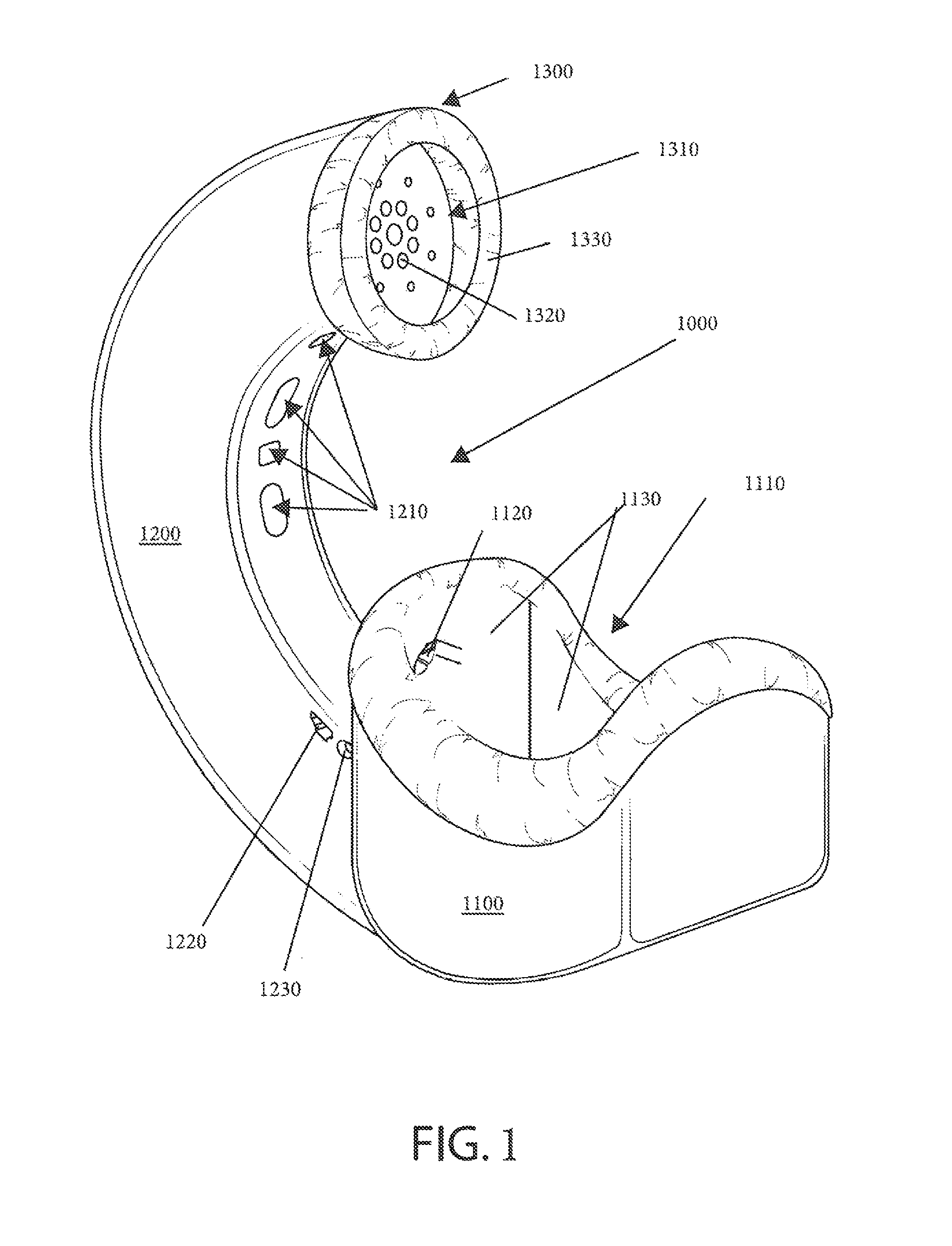
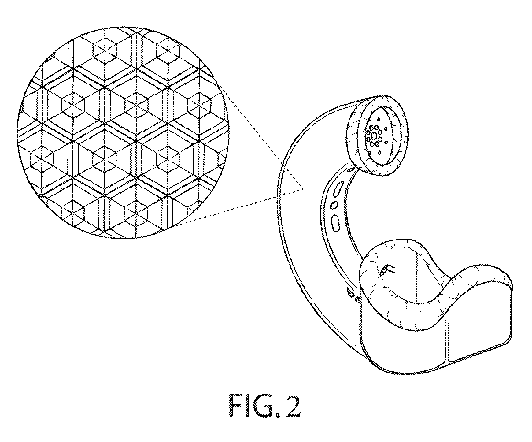
[0014]It is yet a further objective to disclose devices that provide a substantially active noise canceling area over a sound source by causing disruptive interference to all megahertz frequency fields of communicative sounds by male and female speakers. In one embodiment, the device is defined by: a plurality of ANC means antiphase / anti-noise speakers disposed about a receiver portion of a communication device; a support arm for the ANC means and receiver portion; and an ear chamber with an ear opening dampening acoustics about a microphone of a communication device. In a preferred embodiment, the device features electronics software on a printed circuit board (PCB), which measures the sound of a user's voice via a microphone and creates an antiphase noise to cancel the sound of the user's voice in substantially real-time (the best as the software can interpret the speech sounds and create antiphase sound waves). In a preferred embodiment, the ear and ANC means are configured for placement so that the device lies along the mentocervical angle, mentocervical angle length, menton-subnasale length, bitragoin-subnasale arc, or bitragoin-menton arc of a user at a range of nineteen to twenty three degrees. Other embodiments may not incorporate these angles. In use, a mouth may be placed adjacent to the ANC means and receiver portion to position the mouth so that the acoustics of a communicative sound from the mouth are directed toward the receiver portion of the communication device. In a preferred embodiment, air from the user's breath during speech is directed through anti-phase noise created by the ANC means after interaction with the receiver portion of the device for improved acoustic absorption and microphone sound pick-up. The result is voice communication being noise canceled after pickup by the receiver for maintaining privacy of the phone conversation.
[0015]Preferably, the apparatus is configured to fit securely in front of the mouth and over the ear a user, without breaking the seal between the ear opening and the ear of a user. Suitably, this is accomplished via positioning the apparatus at a metocervical angle in a range of fifteen and twenty five degrees relative to the face of a user. Other embodiments need not incorporate these angles. A preferable metocervical angle position for the apparatus is about nineteen degrees for female users and about twenty three degrees for male users. These metocervical angle positions result in the appropriate ear to mouth engagement at an eighty-eighth percentile relationship for both of the bitragion sub-nasale arc and the bitragion-menton arc anthropometric measurements. This insures the provision of an anti-noise coverage area around the entire menton subnasale area (i.e., direct contact area of the entire perimeter of the product's face sound seal) and the center of the ear.

Problems solved by technology

The result is voice communication being noise canceled after pickup by the receiver for maintaining privacy of the phone conversation.

Method used


Image

  • Ergonomic anechoic anti-noise canceling chamber for use with a communication device and related methods
  • Ergonomic anechoic anti-noise canceling chamber for use with a communication device and related methods
  • Ergonomic anechoic anti-noise canceling chamber for use with a communication device and related methods

Examples


Embodiment Construction

[0055]Disclosed, in general, are devices that provide an air-tight chamber over a sound source while trapping, containing, absorbing, directing and deflecting all fields of sounds from the sound source (e.g., the mouth of a human or a woodwind instrument). In general, the devices feature: a specialized anechoic chamber that is configured to receive a sound source in an air-tight manner; and a specialized anechoic channel that is in fluid communication with the ambient atmosphere. Suitably, the anechoic chamber is adapted to capture air containing sound energy generated by the sound source, and distribute the air about an internal surface area on the inside of the chamber, wherein the internal surface area is sufficiently large to dampen or otherwise absorb the sounds energy. Preferably, the air is directed from the anechoic chamber through an anechoic tubular channel extending therefrom to the ambient to further dampen or absorb the sound energy. In one configuration, the outer wall...


PUM


Abstract

Disclosed, in general, are devices that provide a substantially active noise canceling area over a sound source by causing disruptive interference to all frequency fields of speech sounds from the sound source. In some embodiments, active noise control or active noise cancellation means (“ANC means”) are provided to the device. Said means include one or more active noise canceling speakers for the addition of sound specifically designed to cancel noise from the speech sound source without interfering with the sound source going to the microphone, so the listener can clearly hear what the user is saying.

Description

CROSS-REFERENCE TO RELATED APPLICATIONS[0001]This application is a continuation-in-part of U.S. Ser. No. 14 / 943,856 (filed Nov. 17, 2015) and U.S. Ser. No. 14 / 740,129 (filed Jun. 15, 2015), which are continuation-in parts of U.S. Ser. No. 14 / 577,839 (filed Dec. 19, 2014), which is a continuation-in-part to U.S. patent application Ser. No. 14 / 280,523 entitled “Ergonomic tubular anechoic chambers for use with a communication device and related methods” filed on May 16, 2014. Both referenced U.S. Ser. No. 14 / 577,839 and U.S. Ser. No. 14 / 280,523 applications also claim the benefit and priority of U.S. Prov. Pat. App. Ser. No. 61 / 949,239 (filed Mar. 7, 2014) entitled “Accessory having an anechoic chamber for isolating noise of a wind instrument.” Said referenced applications further claim the benefit and priority of U.S. Pat. App. Ser. No. 61 / 949,234 (filed Mar. 6, 2014) entitled “Tubular Anechoic Chamber for Use With a Communication Device.” Said patent applications are hereby incorpora...

Claims


Application Information

Patent Timeline
Patent Type & Authority Patents(United States)
IPC IPC(8): H04M1/00H04R1/08H04R1/10H04M1/03H04M1/19G10K11/178H04R1/34H04R1/22H04M1/05G10K11/16H04M1/17
CPCH04M1/035G10K11/1782H04M1/19H04R1/083H04R1/10H04R1/225H04R1/342G10K11/16G10K2210/108H04M1/05H04M1/17H04R2201/107H04R2499/11H04R9/10H04R2460/01G10K11/17873G10K11/17861G10K11/17857G10K11/17885G10K11/17823G10K11/17815
Inventor MOSER, SCOTT A.
Owner QUIET
Learn More