
Automobile lamp device and method for transmitting signals through light thereof

a technology of auto lamps and lamps, which is applied in the direction of traffic control systems, transportation and packaging, instruments, etc., can solve the problems of large deviation, false alarm and inspection omission, and increase in traffic accidents year by year, so as to improve the driving safety of automobiles and effectively judge potential danger situations

Active Publication Date: 2016-11-29
HASCO VISION TECHNOLOGY CO LTD
View PDF7 Cites 0 Cited by
  • Summary
  • Abstract
  • Description
  • Claims
  • Application Information

AI Technical Summary

Benefits of technology

[0007]The purpose of this invention is to provide automobile lamp device and the method for it to transfer signals through lamplight, realize the signal emitting between the front automobile and rear automobile, effectively judge the potential dangerous situation and improve the driving safety of automobile so as to solve the problem of poor reliability of automotive active safety systems which prevent traffic accidents due to collision of automobile in the existing technology.
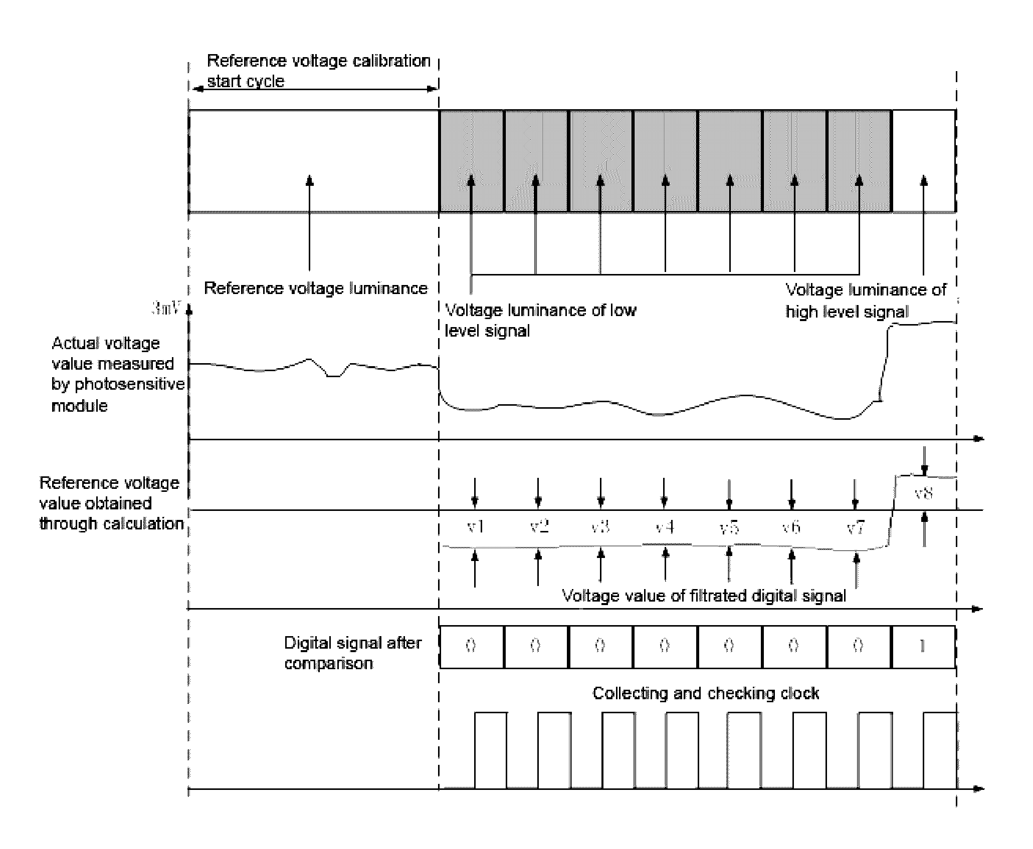
[0018](3) The data signal generator in the signal protocol layer of lamp light emitting apparatus of the front automobile waits for the rising edge of key light signal generated by key light generator, when receiving the rising edge signal, it will, according to the data package generated by data package signal generator, generate data signal waveform. The data signal waveform combines with the key light signal waveform, after signal modulation, analog-modulated luminance signal is generated, and the modulated PWM signal which corresponds to analog-modulated luminance signal will drive the tail lamps through voltage driver and generate optical signal, through the luminance difference of optical signal, the data that needs to be sent will be contained in the ray of tail light, sent to air medium in the form of luminance and received by the rear automobile, thus completing data transmission.
[0035]The beneficial effects achieved by this invention: (1) This invention conducts protocol coding processing for the automobile's operational data collected by bus data receiver in accordance with software protocol layer and signal protocol layer, and sends the encoded data to lamp driver, the latter will drive the luminance of automobile tail lamps; through the difference of tail light luminance, the data that needs to be sent is contained in the ray of tail lamps, so as to effectively realize the communication between automobile, lamps and automobile and lamps; it's helpful to realize intelligent transportation and intelligent automobile, thus improving the driving safety and effectively reducing the potential accidents.
[0036](2) This invention enables the drivers and automobile to realize information interaction in the form of quantifiable information—digit, it can make the computer more accurately judge the status of automobile around the driving environment, precisely judge the potential danger and improve driving safety; at the same time, this invention is also helpful to realize car networking and provide effective equipment support for intelligent transportation and network transportation.

Problems solved by technology

But with the constant improvement of automobile usage rate, traffic accidents also present a rising trend year by year.
For example, the active safety system based on camera sensor will generate false alarm and inspection omission when working at night; the active safety system based on radar sensor will present large deviation in the automobile lateral motion component.
These defects will make the systems lose their functions and significances.

Method used


Image

  • Automobile lamp device and method for transmitting signals through light thereof
  • Automobile lamp device and method for transmitting signals through light thereof
  • Automobile lamp device and method for transmitting signals through light thereof

Examples


Embodiment Construction

[0051]Next, this invention will be further explained in detail by combining with the figures. Example of device implementation for this invention:

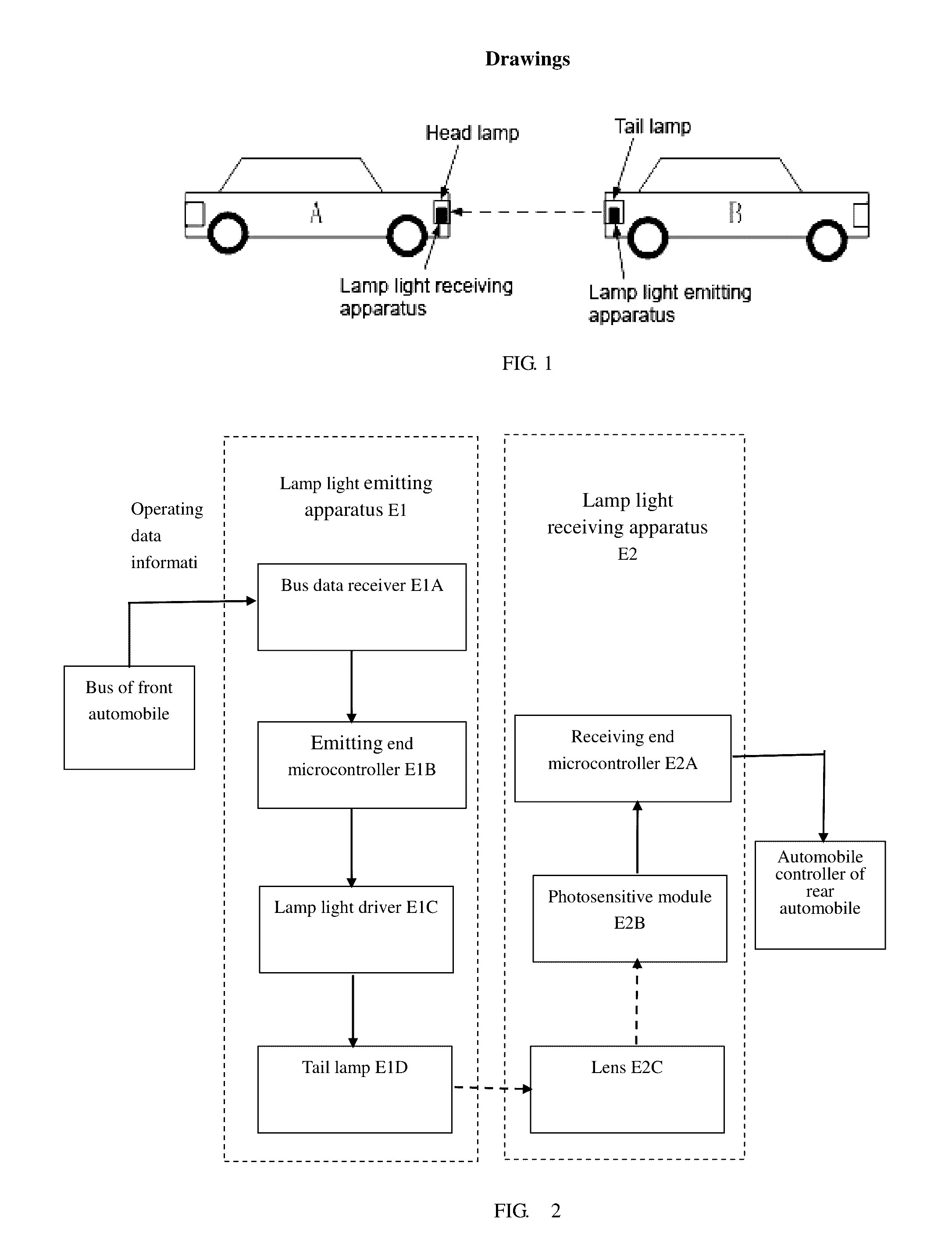
[0052]As shown in FIG. 1, the lamp device in this invention includes the head lamps installed at the head of the automobile and the tail lamps installed at the tail of the automobile; inside the head lamp, there is lamp light emitting apparatus E1 and inside the tail light, there is lamp light receiving apparatus E2.

[0053]In this implementation example, the lamp light emitting apparatus is mounted on the CAN bus of automobile, collect the data that the automobile itself needs to send, such as speed data, brake pedal data and accelerator data, etc; when automobile A travels to the rear of automobile B, because the lamp light receiving apparatus in head lamp of automobile A aligns with the lamp light emitting apparatus in tail light of automobile B, automobile A can receive the data sent by automobile B, such as speed data, brake pedal data ...


PUM


Abstract

It divides the network communication protocol for the communication between automobile into a software protocol layer (L1), a signal protocol layer and a physical protocol layer wherein the software protocol layer is used for checking coding and decoding the data required to be sent and received by a system, and the signal protocol layer is used for performing combined coding of data package signals and basic light signal on data packages produced by the software protocol layer according to the protocol agreement, and the physical protocol layer is used for converting digital signals and light signals mutually. A device comprises a light receiving apparatus arranged at the head of the automobile and a light emitting device, which collects the operating status information of automobile, performs information exchange with surrounding automobiles through digital information, arranged at the tail of the automobile.

Description

[0001]This application is the U.S. national phase of International Application No. PCT / CN2013 / 089775 Filed on on 18 Dec. 2013 which designated the U.S. and claims priority to Chinese Application Nos. CN201310533122.2 filed on 30 Oct. 2013, the entire contents of each of which are hereby incorporated by reference.FIELD OF THE INVENTION[0002]This invention involves intelligent transportation and intelligent automobile research field, to be specific, it involves an automobile lamp device and a method for emitting signals through light thereof.BACKGROUND OF THE INVENTION[0003]With the continuous development of economy and transportation, automobiles have become people's indispensable means of transportation. But with the constant improvement of automobile usage rate, traffic accidents also present a rising trend year by year. According to statistics, in all motor automobile accidents, the traffic accidents caused by lane departure account for twenty percent of all traffic accidents, the...

Claims


Application Information

Patent Timeline
Patent Type & Authority Patents(United States)
IPC IPC(8): B60W30/09G08G1/16H04L29/06G07C5/00G08C23/04
CPCB60W30/09G07C5/008G08C23/04G08G1/163H04L65/00G08G1/166B60Q1/0023B60W2420/00B60W2420/42B60W2556/65
Inventor ZHOU, SHENGYANAO, JINLONGLI, JINGQUANZHANG, YUAN
Owner HASCO VISION TECHNOLOGY CO LTD
Learn More