
Rearview mirror apparatus and car thereof

Inactive Publication Date: 2019-10-17
QUISDA CORP
View PDF14 Cites 0 Cited by
  • Summary
  • Abstract
  • Description
  • Claims
  • Application Information

AI Technical Summary

Benefits of technology

The present invention is a monitoring device that is placed on the rearview mirror casing and can rotate to align with the pivoting angle of the rearview mirror casing. This allows the display monitor to show the surveillance images of the car's blind spot area and the front window pillar area simultaneously. The invention solves the prior art problem of not having monitoring in the left or right surrounding area of the car, which improves driving safety.

Problems solved by technology

However, the aforesaid sensing design can only perform safety monitoring on the front and rear surrounding areas of the car (e.g. reverse monitoring) rather than the left or right surrounding area of the car.
Furthermore, the driver's vision could be easily blocked by the frame structure of the car, and the left, central, right rearview mirrors of the car could only provide a narrow driving vision.
Thus, the driver cannot grasp the whole situation around the car since the aforesaid problems may cause blind spot areas when the driver is driving the car.

Method used


Image

  • Rearview mirror apparatus and car thereof
  • Rearview mirror apparatus and car thereof
  • Rearview mirror apparatus and car thereof

Examples


Embodiment Construction

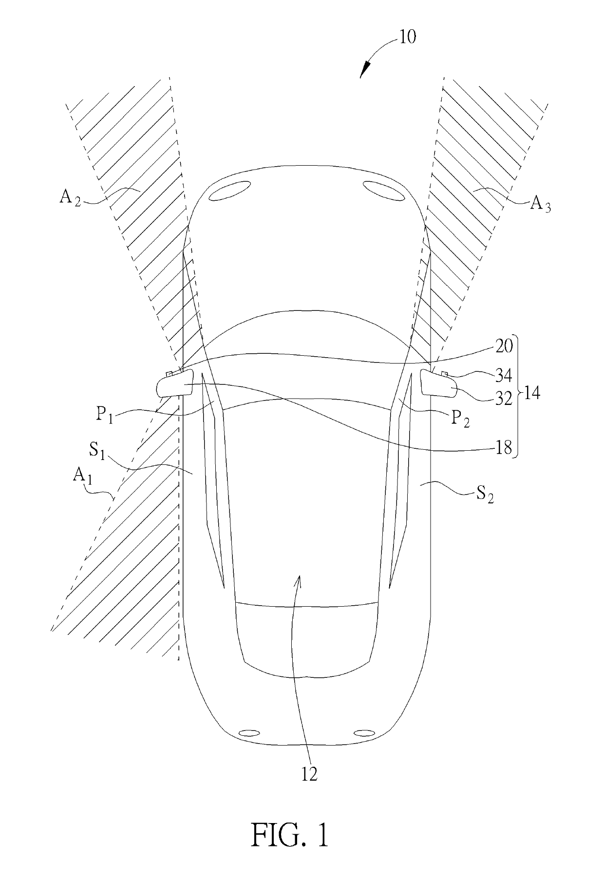
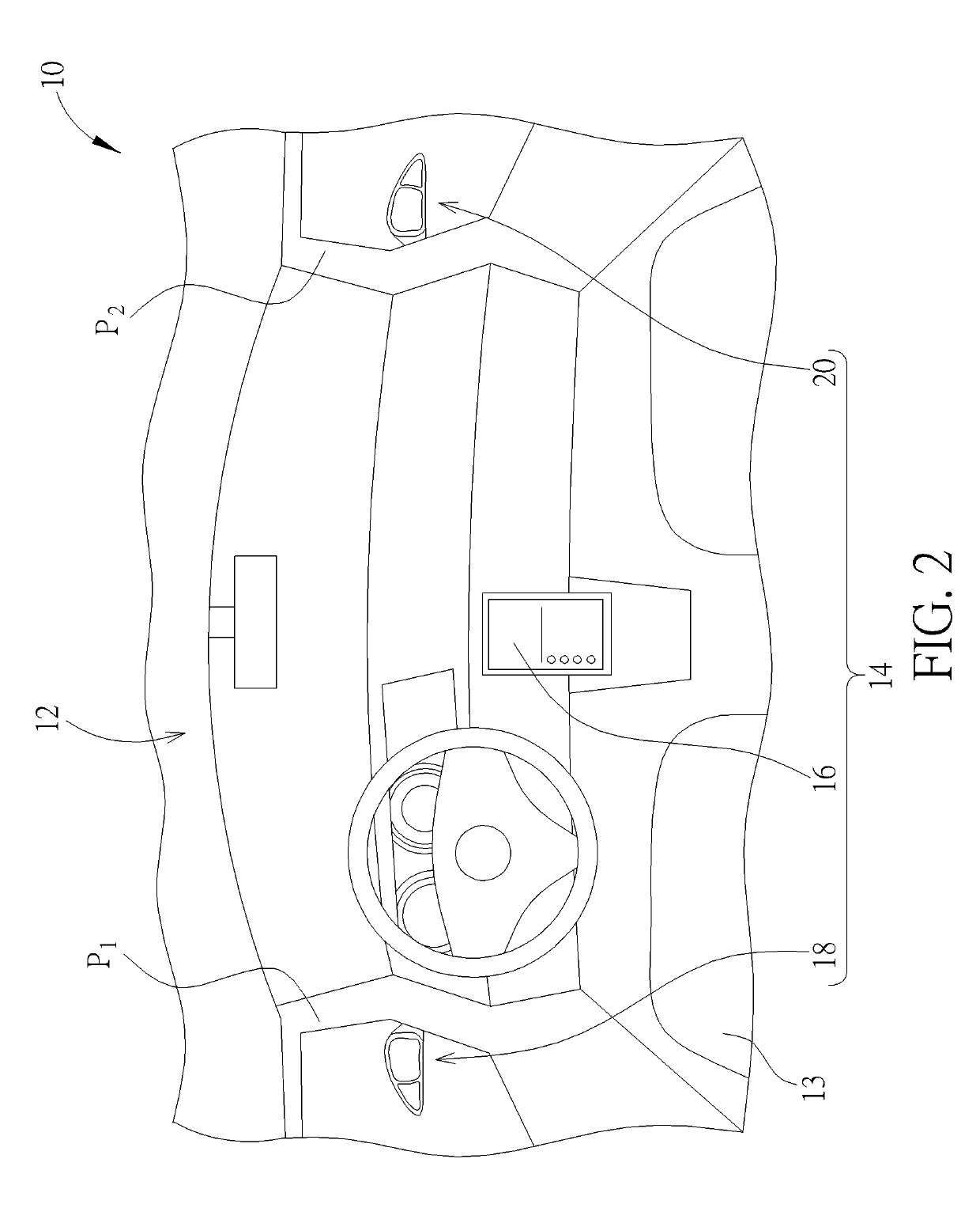
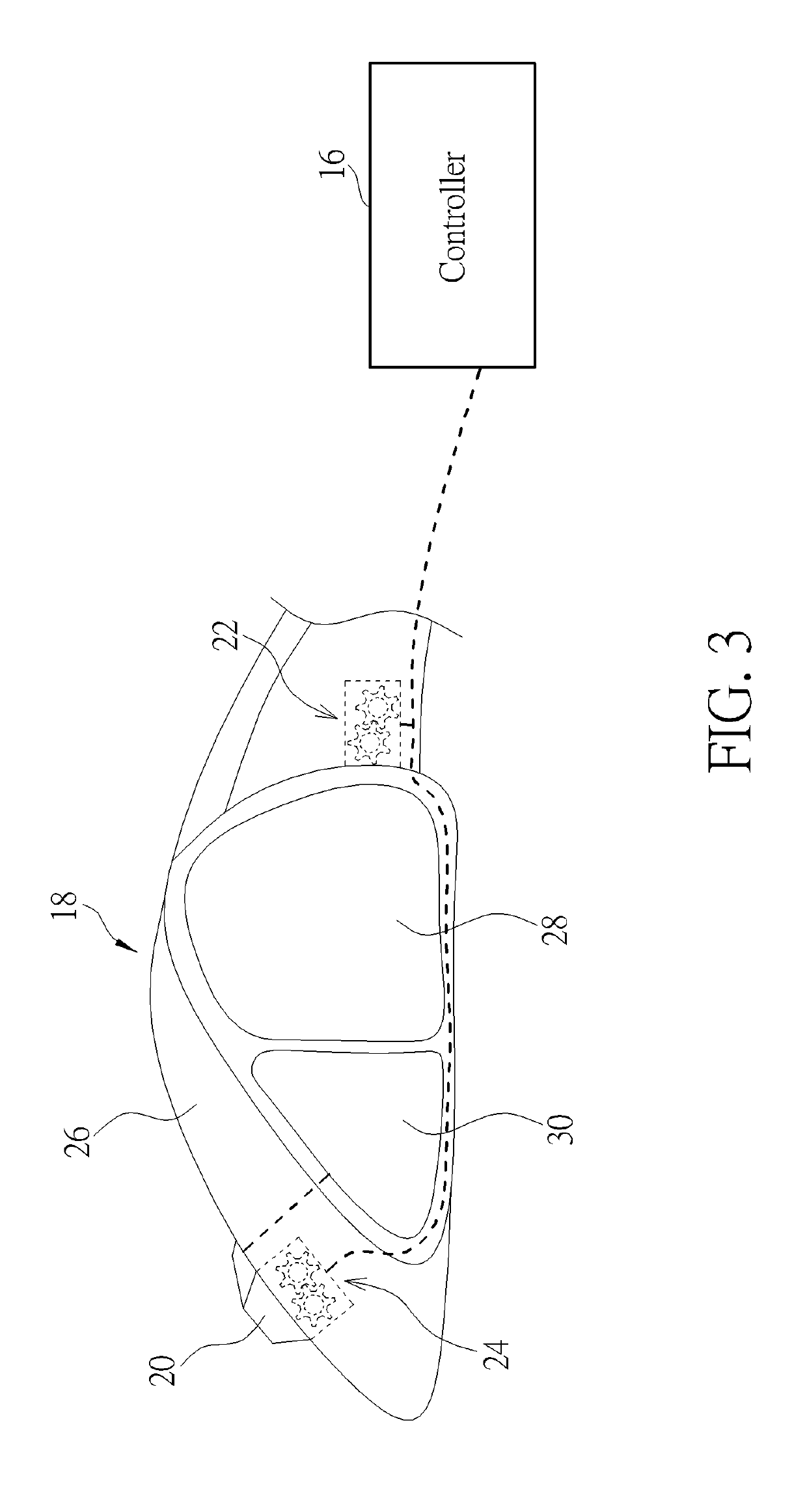
[0011]Please refer to FIG. 1 and FIG. 2. FIG. 1 is a diagram of a car 10 according to an embodiment of the present invention. FIG. 2 is a partial internal diagram of the car 10 in FIG. 1. As shown in FIG. 1 and FIG. 2, the car 10 includes a car body 12, a rearview mirror apparatus 14, and a controller 16. The car body 12 could have a first front window pillar P1, a second front window pillar P2, and a driver seat 13 (preferably suitable for a left-hand drive car, but not limited thereto) . The first front window pillar P1 is adjacent to the driver seat 13, and the second front window pillar P2 is away from the driver seat 13. As for the related description for other components (e.g. a car engine and an automobile chassis mechanism) of the car body 12, it is commonly seen in the prior art and omitted herein. The rearview mirror apparatus 14 is connected to the car body 12. The controller 16 could be preferably a control host (e.g. a car control panel) disposed in the car body 12, but...


PUM


Abstract

A rearview mirror apparatus for connecting to a car includes a rearview mirror device pivoted to the car, first and second gear devices, a monitoring device, and a controller coupled to the first and second gear devices. The first gear device is connected to the rearview mirror device for rotating the rearview mirror device relative to the car. The monitoring device is pivoted to the rearview mirror device for monitoring a surrounding area of the car. The second gear device is connected to the monitoring device for rotating the monitoring device relative to the rearview mirror device. When the controller controls the first gear device to rotate the rearview mirror device by a pivoting angle, the controller controls the second gear device to rotate the monitoring device by a compensation angle according to the pivoting angle for aligning the monitoring device with the surrounding area.

Description

BACKGROUND OF THE INVENTION1. Field of the Invention[0001]The present invention relates to a rearview mirror apparatus and a car thereof, and more specifically, to a rearview mirror apparatus disposing a monitoring device on a rearview mirror device for rotating the monitoring device by a compensation angle according to a pivoting angle of the rearview mirror device and a car thereof.2. Description of the Prior Art[0002]In general, for efficiently preventing a car from colliding with an object (e.g. a utility pole) while the car is moving forward or backward, infrared light sensors are usually disposed on front and rear bumpers of the car and produce a warning sound when the car is too close to the object, so as to remind a driver of braking the car in time.[0003]However, the aforesaid sensing design can only perform safety monitoring on the front and rear surrounding areas of the car (e.g. reverse monitoring) rather than the left or right surrounding area of the car. Furthermore, t...

Claims


Application Information

Patent Timeline
IPC IPC(8): B60R1/00B60R1/08B60R1/12
CPCB60R1/12B60R1/081B60R2001/1223B60R2001/1253B60R1/007B60R1/00B60R2001/1215B60R2300/802B60R11/04B60R2011/004B60R2011/0085
Inventor TUNG, HAO-CHUN
Owner QUISDA CORP
Learn More